Plasma processing apparatus and method

Inactive Publication Date: 2007-03-08
HITACHI HIGH-TECH CORP
View PDF3 Cites 23 Cited by
  • Summary
  • Abstract
  • Description
  • Claims
  • Application Information

AI Technical Summary

Benefits of technology

[0014] The present invention has been made in consideration of these problems, and provides plasma processing techniques capable of detecting beforehand generation of a working defect and correctly predicting the process result without using a dummy wafer whose surface state is already man

Problems solved by technology

However, according to the techniques disclosed in JP-A-2002-100611 and the like, for example, even if generation of an abnormal state is predicted which is so severe that the correct process result cannot be obtained only by the process condition adjustment, it is inevitable that a wafer already being processed becomes defective.
Therefore, although these techniques are effective for lowering a defect rate, the techniques are not sufficient for predicting generation of a defect and preventing the defect in advance.
Particularly in recent years, since the degree of fineness and c

Method used


Image

  • Plasma processing apparatus and method
  • Plasma processing apparatus and method
  • Plasma processing apparatus and method

Examples


first embodiment

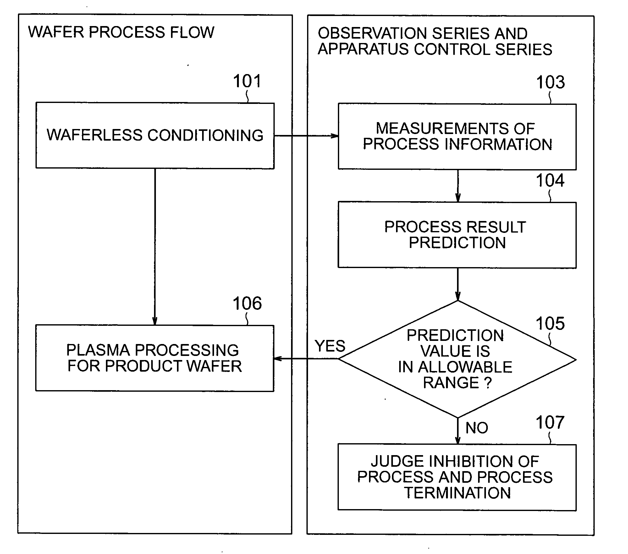
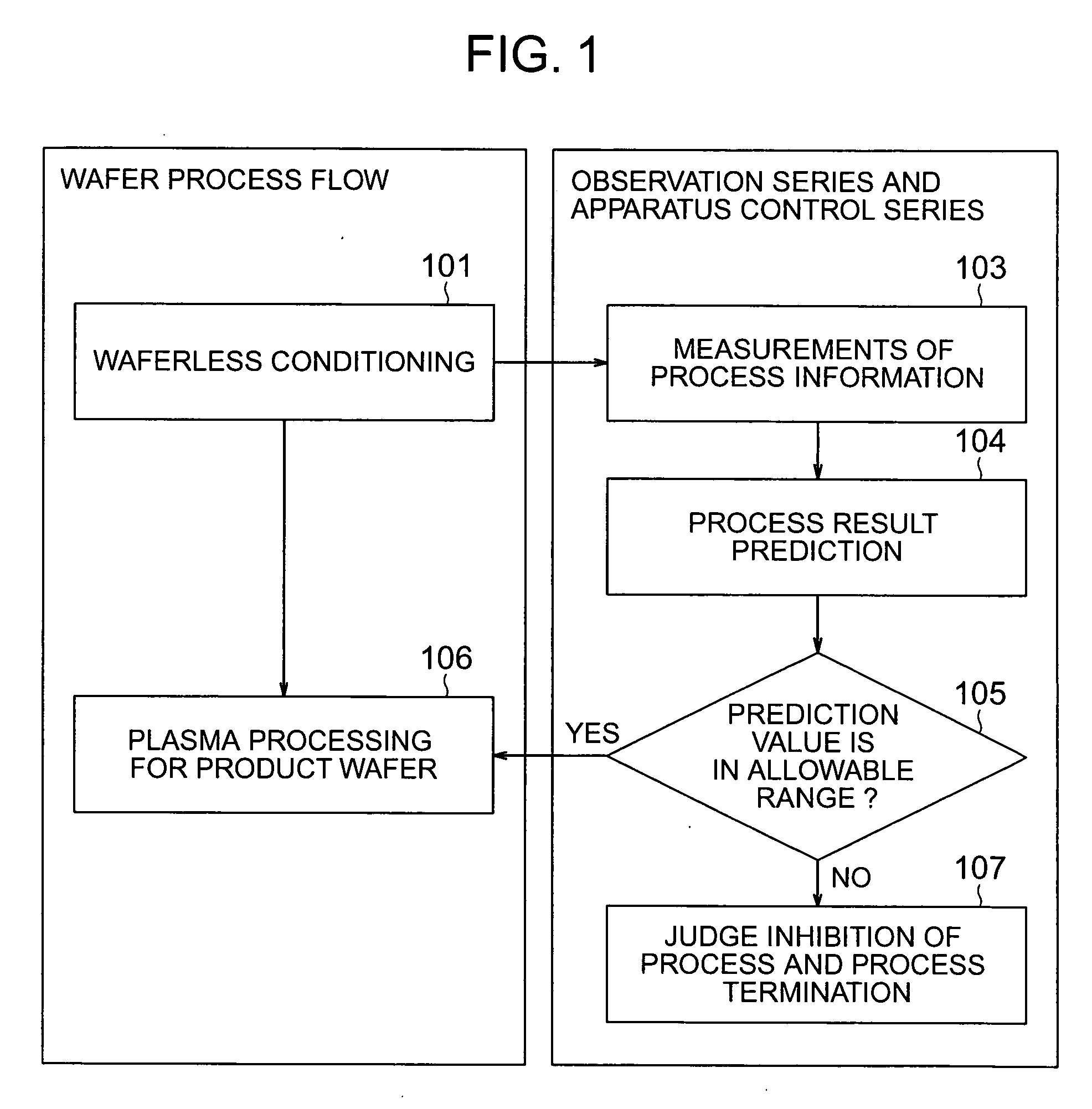
[0042] Embodiments will be described with reference to the accompanying drawings. FIG. 1 is a diagram illustrating a process sequence according to the present invention, and this process sequence will be described by comparing it with the process sequence of conventional techniques shown in FIG. 2.

[0043] According to the conventional techniques shown in FIG. 2, an N-th wafer is subjected to a plasma process 106, and measurements 103 are performed to acquire process information such as an emission spectrum of plasma, temperatures in a plasma processing chamber and / or the like. A prediction 104 is performed to predict a process result of the N-th wafer from the results of the measurements 103. A judgement 105 is performed on the basis of a prediction value, and if the prediction value of the process result of the N-th product wafer is in an allowable range, a process 106 starts for an (N+1)-th wafer.

[0044] Prior to the process 106, waterless conditioning 151 is performed to remove ch...

second embodiment

[0097] This can be applied to detecting the end point of the For example, if the end point of the product wafer 257B is not still obtained although the prediction value of the product wafer 257A enters the normal range and the end point is obtained, the waferless conditioning 101 continues to provide a high reliability plasma process for both the product wafers. Alternatively, if the product wafer 257A is to be processed, the waterless conditioning 101 is terminated at the end point of only the product wafer 257A, and conversely if the product wafer 257B is to be processed, the waferless conditioning 101 is terminated at the end point of only the product wafer 257B. In this manner the state, i.e., process environment of the inner wall surface of the plasma processing chamber 250, can be used selectively between the product wafers 257A and 257B.

[0098] In the above description, although two types of the product wafers 257A and 257B are used, for example, the product wafer 257A may ha...

third embodiment

[0107] As described above, if the prediction value does not enter the normal range, the necessary condition of the recovery step 503 is set in accordance with the prediction value. By using two or more prediction values, the state of the apparatus can be judged synthetically and a more suitable condition of the recovery step 503 can be set.

[0108]FIG. 15 is a diagram showing the fourth embodiment of the present invention. In this embodiment, description will be made on a recovery method after maintenance of the plasma processing apparatus. The fourth embodiment may be combined with the end point detection method of the second embodiment or the recovery step 503 of the third embodiment.

[0109] First, while the processing apparatus operates normally, a step 601 generates beforehand the prediction equation of a test wafer 257T. The particular sequence of this step 601 is similar to the operation sequence of the first embodiment shown in FIG. 8.

[0110] Next, when the apparatus is stoppe...


PUM

PropertyMeasurementUnit
Plasma poweraaaaaaaaaa
Electric fieldaaaaaaaaaa

Abstract

A plasma processing apparatus includes: a processing chamber; a state detector for detecting a state of plasma in the processing chamber; an input unit for inputting process result data of a specimen processed in the plasma processing chamber; and a controller including a prediction equation forming unit for forming a prediction equation of a process result in accordance with plasma state data detected with the state detector for the plasma process simulating a specimen existing state in the processing chamber in a specimen non-placed state and process result data of the specimen input with the input unit and processed by the plasma process in a specimen placed state, and storing the prediction equation, wherein the controller predicts the process result of a succeeding plasma process in accordance with plasma state data newly acquired via the state detector in the specimen non-placed state and the stored prediction equation.

Description

BACKGROUND OF THE INVENTION [0001] 1. Field of the Invention [0002] The present invention relates to plasma processing techniques, and more particularly to plasma processing techniques capable of executing an optimum process by predicting the result of a plasma process. [0003] 2. Description of the Related Art [0004] The dimensions of semiconductor devices have become fine year after year. Therefore, requirement for a work precision have become severe. A variation of even several nm or smaller may cause defective devices. [0005] In a plasma processing apparatus for physically and chemically processing semiconductor wafers by decomposing process gasses by plasma, chemical substances and the like generated inside the apparatus are attached to and remain on the inner wall of a plasma processing chamber. This influences the wafer process in many cases. Therefore, even if the process conditions are maintained constant, the process result such as a patterning size changes as the wafer pro...

Claims


Application Information

Patent Timeline
IPC IPC(8): B08B3/12B08B6/00G06F19/00C23C16/00C23F1/00H01L21/3065
CPCH01J37/32935B08B7/0035H01L21/3065
Inventor IWAKOSHI, TAKEHISATANAKA, JUNICHIKITSUNAI, HIROYUKIMASUDA, TOSHIOSHIRAISHI, DAISUKE
Owner HITACHI HIGH-TECH CORP
Why Eureka
Try Eureka