Optical detection apparatus and method thereof

a detection apparatus and optical image technology, applied in the direction of optical radiation measurement, luminescent dosimeters, instruments, etc., can solve the problems of limited spot size, increased hardware cost of precise devices, and optical limitation of diffraction, so as to reduce the dark current

Inactive Publication Date: 2007-03-08
DR CHIP BIOTECH
View PDF15 Cites 8 Cited by
  • Summary
  • Abstract
  • Description
  • Claims
  • Application Information

AI Technical Summary

Benefits of technology

[0019] The light receiver has an image-sensing module, such as a charge-coupled...

Problems solved by technology

However, the size of the spot is restricted by the optical limitation of diffraction and the wavelength of the incident light.
The precise device increases the hardware cost.
The single point scanning also increases the imaging time and slows the operation.
When omitting the dichroic mirror, the optical des...

Method used


Image

  • Optical detection apparatus and method thereof
  • Optical detection apparatus and method thereof
  • Optical detection apparatus and method thereof

Examples


Embodiment Construction

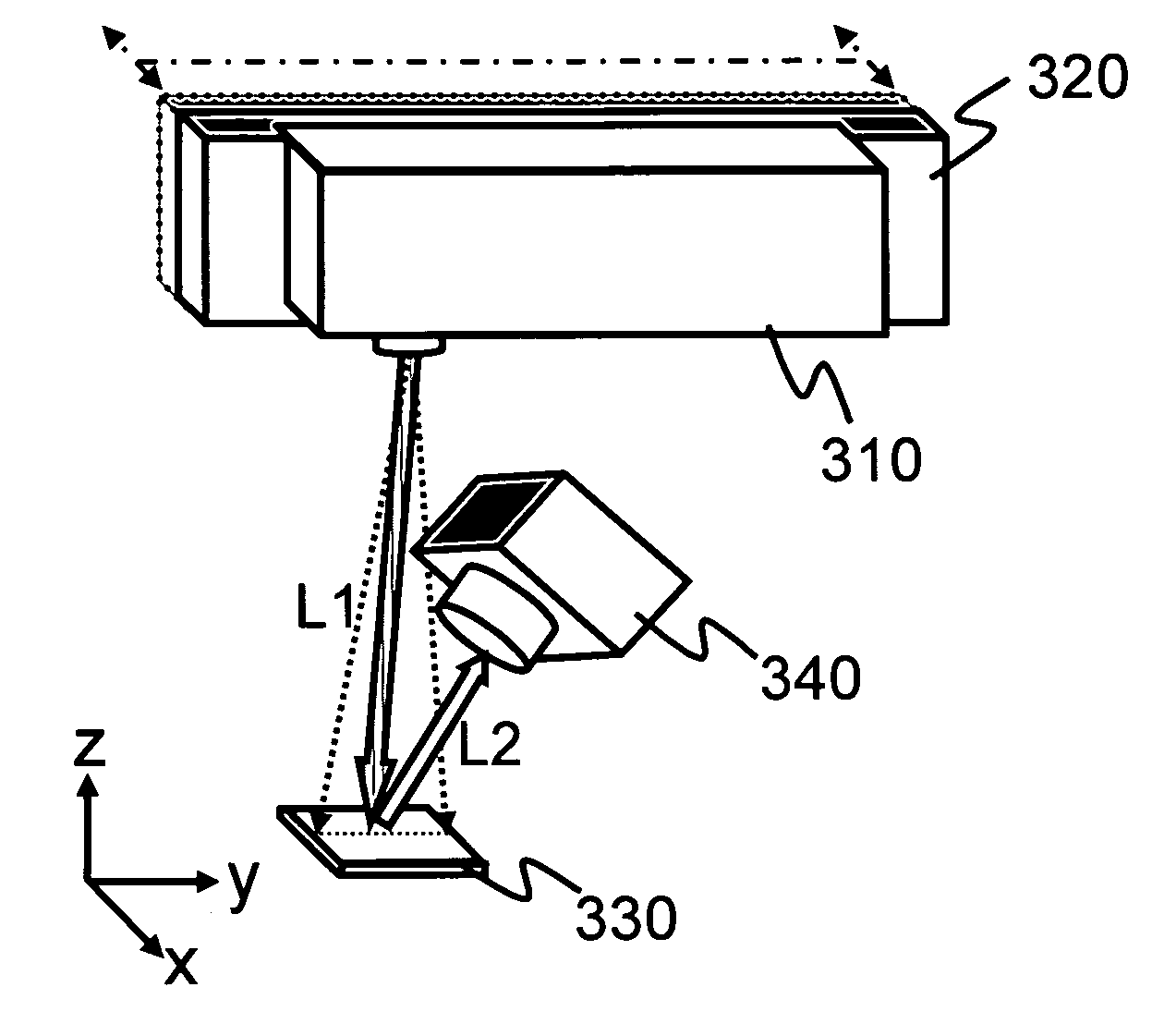
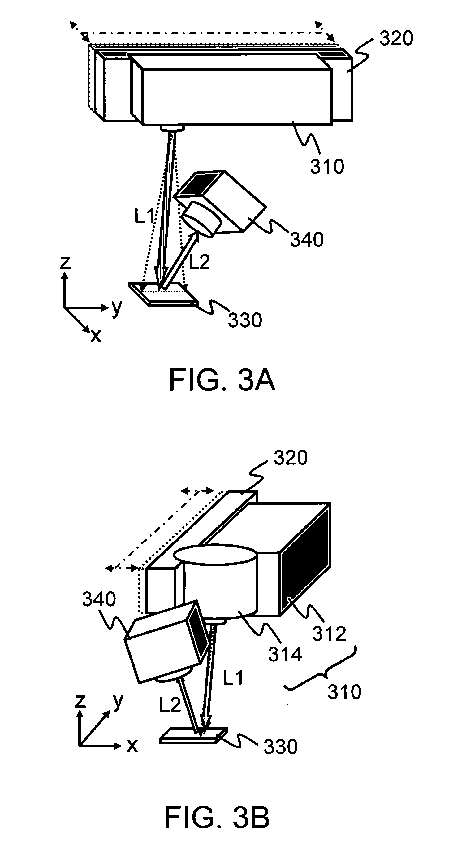
[0038] As shown in FIG. 3A, an optical detection apparatus according to a first embodiment of the invention is illustrated. In this case, a light module 310 generates excitation light L1 scanning in Y-axis, and the light module 310 is carried by a carrier 320 to move in a direction nonparallel to Y-axis, so as to achieve two-dimensional scanning. The preferred direction is along X-axis. In other words, the excitation light L1 scanning in Y-axis and moving along X-axis is combined to produce a two-dimensional testing zone in which a labeled sample 330 is placed. The labeled sample 330 excited by the linear scanning light to emit emission light L2. A light receiver 340 receives the emission light L2 and processes to form image signals of the labeled sample 330.

[0039] In this case, the labeled sample is a test sample labeled with or having fluorescent compounds, or colorimetric compounds. The fluorescent compounds may be fluorescent groups, quantum dot particles, other dye particles o...


PUM


Abstract

An optical detection apparatus and method thereof is provided, which is applicable for detecting the image signals of a labeled sample. First, a laser module provides excitation light, and the excitation light is continuously reflected by a scan module for providing linear scanning light by changing a reflection angle. The carrier moves the light module in a direction nonparallel to the linear direction so as to provide a two-dimensional testing zone. The labeled sample placed in the testing zone is excited by the linear scanning light and generates emission light to be received by the light receiver. Therefore, the light receiver forms the image signals of the labeled sample corresponding to the emission light.

Description

BACKGROUND [0001] 1. Field of the Invention [0002] The invention relates to an apparatus and method for detecting optical signals, and particularly to an apparatus and method for detecting two-dimension optical image signals. [0003] 2. Description of the Related Art [0004]FIG. 1 shows a systematic view of a general apparatus for fluorescence signals detection. A sampling light beam L1′ passes an excitation filter or a monochromator 110. The filter or monochromator 110 lets the excitation laser L1 pass through and irradiate the labeled sample 120 in the testing zone. The labeled sample 120 is excitated to radiate fluorescence. The emission light L2 passes a second filter or a monochromator 112 where unneeded noise light is removed. Then, a monochromical emission is detected by a photodetector 130. [0005] There are two technical manners for detecting fluorescence signals. The first manner is to apply laser as an excitation light and apply a photomultiplier tube (PMT) to detect the rec...

Claims


Application Information

Patent Timeline
IPC IPC(8): G01J1/58
CPCG01N21/6428G01N21/6452G01N21/6456G02B21/0076G02B21/0036G02B21/0048G02B21/0064G01N2201/105
Inventor CHEN, CHIEN-ANWANG, HAN-WEIHUNG, CHI-FU
Owner DR CHIP BIOTECH
Why Eureka
Try Eureka