Manufacturing method of high-pressure discharge lamp, high-pressure discharge lamp, lamp unit using high-pressure discharge lamp, and image display apparatus using high-pressure discharge lamp

a manufacturing method and discharge lamp technology, applied in the manufacture of electric discharge tubes/lamps, discharge tubes luminescnet screens, discharge tubes/lamp factory adjustments, etc., can solve the problems of halogen cycle not working, devitrification and blackening, etc., and achieve the effect of lowering the progression rate of devitrification

Active Publication Date: 2007-03-08
PANASONIC CORP
View PDF14 Cites 8 Cited by
  • Summary
  • Abstract
  • Description
  • Claims
  • Application Information

AI Technical Summary

Benefits of technology

[0024] This can reduce devitrification of the light emission part, and prevent blackening of an internal surface of the light emission part while the lamp is used. Here, since at least the light emission part of the translucent vessel is kept at a predetermined temperature or higher, a diffusion speed of the impurities in the material forming the light emission part can be increased.
[0056] This image display apparatus uses a lamp unit that has an improved illuminance maintenance factor, as a light source. Therefore, the image display apparatus has a higher illuminance maintenance factor regarding an image projected on a screen or the like. In addition, change of the lamp unit is required less often, which can reduce a maintenance cost.

Problems solved by technology

This causes devitrification.
Furthermore, the interfused alkali metals interrupt a halogen cycle, so that the halogen cycle does not work.
This causes blackening.
In addition, even in a case where VyCol glass and mercury bromide are not used to form the lamp, devitrification and blackening may occur when the constituents (e.g. electrodes and quartz glass) of the lamp contain a great deal of alkali metals, or when a great deal of alkali metals are interfused into the light emission part of the translucent vessel during the manufacturing process.

Method used


Image

  • Manufacturing method of high-pressure discharge lamp, high-pressure discharge lamp, lamp unit using high-pressure discharge lamp, and image display apparatus using high-pressure discharge lamp
  • Manufacturing method of high-pressure discharge lamp, high-pressure discharge lamp, lamp unit using high-pressure discharge lamp, and image display apparatus using high-pressure discharge lamp
  • Manufacturing method of high-pressure discharge lamp, high-pressure discharge lamp, lamp unit using high-pressure discharge lamp, and image display apparatus using high-pressure discharge lamp

Examples


first embodiment

(1) Construction of Lamp Unit

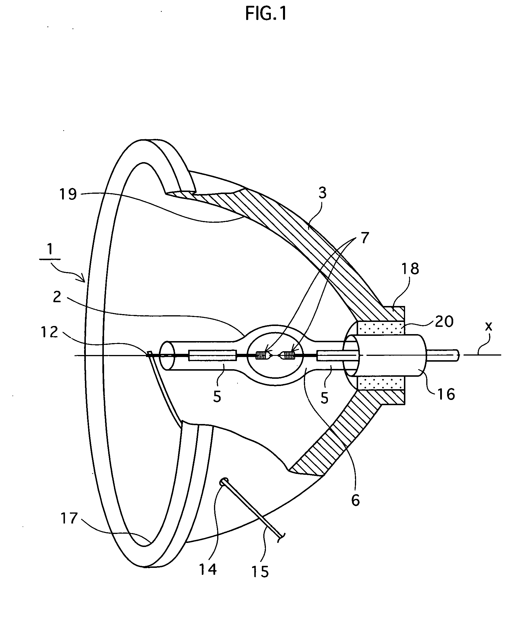
[0076]FIG. 1 is a perspective view illustrating a construction of a lamp unit 1 for a projector, relating to a first embodiment of the present invention, with a part broken away to show an inner structure.

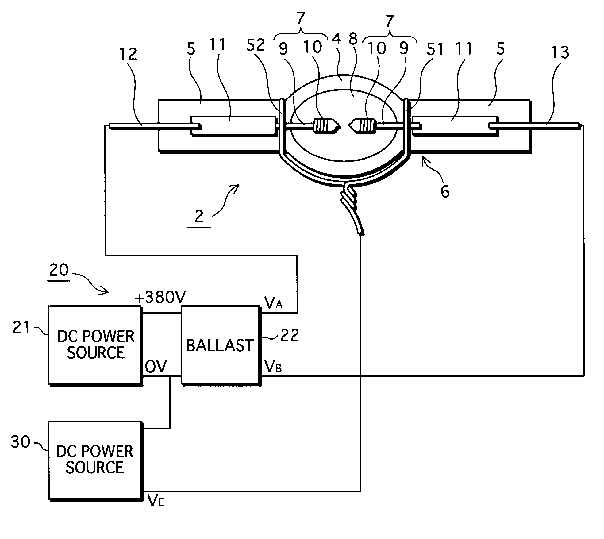
[0077] As shown in FIG. 1, the lamp unit 1 includes a high-pressure mercury lamp 2 and a concave reflector 3. Here, the high-pressure mercury lamp 2 is positioned in the concave reflector 3 in such a manner that a middle point between paired electrodes 7 of the high-pressure mercury lamp 2 substantially coincides with a focal point of the concave reflector 3, and that a lengthwise central axis X of the high-pressure mercury lamp 2 is substantially parallel to an optical axis of the concave reflector 3 (In FIG. 1, the lengthwise central axis X coincides with the optical axis.) The high-pressure mercury lamp 2 is an AC-powered type, and has a rated power of 220 W.

[0078] The concave reflector 3 has an opening 17 in front, and a neck part 18 at back. An...

second embodiment

[0159] The following describes a lamp unit for a projector, relating to a second embodiment of the present invention. The lamp unit relating to the second embodiment has the same construction as the lamp unit 1 relating to the first embodiment. However, the high-pressure mercury lamp 2 included in the lamp unit relating to the second embodiment is obtained by using a manufacturing method different from the manufacturing method described in the first embodiment.

[0160] The manufacturing method for the high-pressure mercury lamp 2 for use in the lamp unit relating to the second embodiment is different from the manufacturing method described in the first embodiment, only in terms of the electric field application step. This difference is described in the following.

[0161] After the lamp formation step is completed, the high-pressure mercury lamp 2 is horizontally kept as shown in FIG. 13. In addition, flat rectangular conductive members 54 and 55, which are made of copper and have a pl...

third embodiment

[0171] The following describes a lamp unit for a projector, relating to a third embodiment of the present invention. According to the first and second embodiments, impurities such as alkali metals are eliminated from the discharge space or translucent vessel 6 during the manufacturing process of the high-pressure mercury lamp 2. However, the lamp unit relating to the third embodiment is characterized in that impurities are eliminated while a high-pressure mercury lamp actually operates.

(1) Construction of Lamp Unit 201

[0172] As shown in FIG. 14, a lamp unit 201 for a projector, relating to the third embodiment of the present invention, is formed by arranging an AC-powered high-pressure mercury lamp 202 having a rated power of 220 W in a concave reflector 203. Here, the high-pressure mercury lamp 202 is positioned in the concave reflector 203 in such a manner that a middle point between paired electrodes 209 (mentioned later) substantially coincides with a focal point of the concav...


PUM


Abstract

A manufacturing method of a high-pressure mercury lamp includes an electric field application step in which an electric field is applied to at least a light emission part (4) with the high-pressure mercury lamp being kept at a high temperature. This can reduce impurities such as hydrogen and alkali metals in a discharge space (8) and glass forming the light emission part (4). As a consequence, blackening and devitrification of the high-pressure mercury lamp while the lamp is lit can be reduced.

Description

TECHNICAL FIELD [0001] The present invention relates to a manufacturing method of a high-pressure discharge lamp, a high-pressure discharge lamp, a lamp unit using the high-pressure discharge lamp, and an image display apparatus using the high-pressure discharge lamp. BACKGROUND ART [0002] In recent years, image display apparatuses, such as liquid crystal projectors and digital light processing (DLP) projectors, are increasingly used for systems to project broadcast and played-back images or to make presentations with the use of personal computers. [0003] Such image display apparatuses use, as a light source, a short-arc high-pressure mercury lamp (for example, Japanese patent application publication No. H02-148561) which is substantially a point light source. [0004] This high-pressure mercury lamp includes a light emission part having a pair of electrodes therein, and sealed parts which extend from different ends of the light emission part. In each of the sealed parts, a metal foil...

Claims


Application Information

Patent Timeline
Patent Type & Authority Applications(United States)
IPC IPC(8): H05B41/14H01J9/24H01J9/44H01J61/26H01J61/82H05B41/292
CPCH01J9/247H01J9/44H05B41/2928H01J61/822H01J61/26
Inventor SAKAGUCHI, JUNONO, SYUNSUKEKURIMOTO, YOSHITAKASHIMIZU, TOSHIYUKIHATAOKA, SHINICHIROTAKAHASHI, KIYOSHITSUTATANI, TAKASHISEKI, TOMOYUKIHORIUCHI, MAKOTOICHIBAKASE, TSUYOSHI
Owner PANASONIC CORP
Why Eureka
Try Eureka