Bobbin for superconducting coil, and superconducting solenoid coil

a superconducting coil and superconducting solenoid technology, applied in the direction of superconducting magnets/coils, magnetic bodies, instruments, etc., can solve the problems of easy shortening of oxygen inside the coil, serious distortion, and difficulty in insulating the coil, and achieves easy, smooth, and helically wound wound

Inactive Publication Date: 2007-03-08
KOBE STEEL LTD
View PDF2 Cites 11 Cited by
  • Summary
  • Abstract
  • Description
  • Claims
  • Application Information

AI Technical Summary

Benefits of technology

[0012] The bobbin of the present invention has an extremely simple structure in which the tapered portion having the tapered surface inclined at an arbitrary angle is provided at each end of the drum. With this structure, a tape-like superconducting wire or a precursor thereof can be easily, smoothly, and helically wound to form a subsequent layer with little distortio

Problems solved by technology

On the other hand, since the wire closely wound into a coil is heated while supplying oxygen thereto from the outside, oxygen easily runs short inside the coil.
Moreover, it has been pointed out that insulating the coil is difficult because heating is performed at high temperature after winding.
However, when a superconducting wire is helically (solenoidally) wound to form a plurality of layers, it is seriously distorte

Method used


Image

  • Bobbin for superconducting coil, and superconducting solenoid coil
  • Bobbin for superconducting coil, and superconducting solenoid coil
  • Bobbin for superconducting coil, and superconducting solenoid coil

Examples


first example

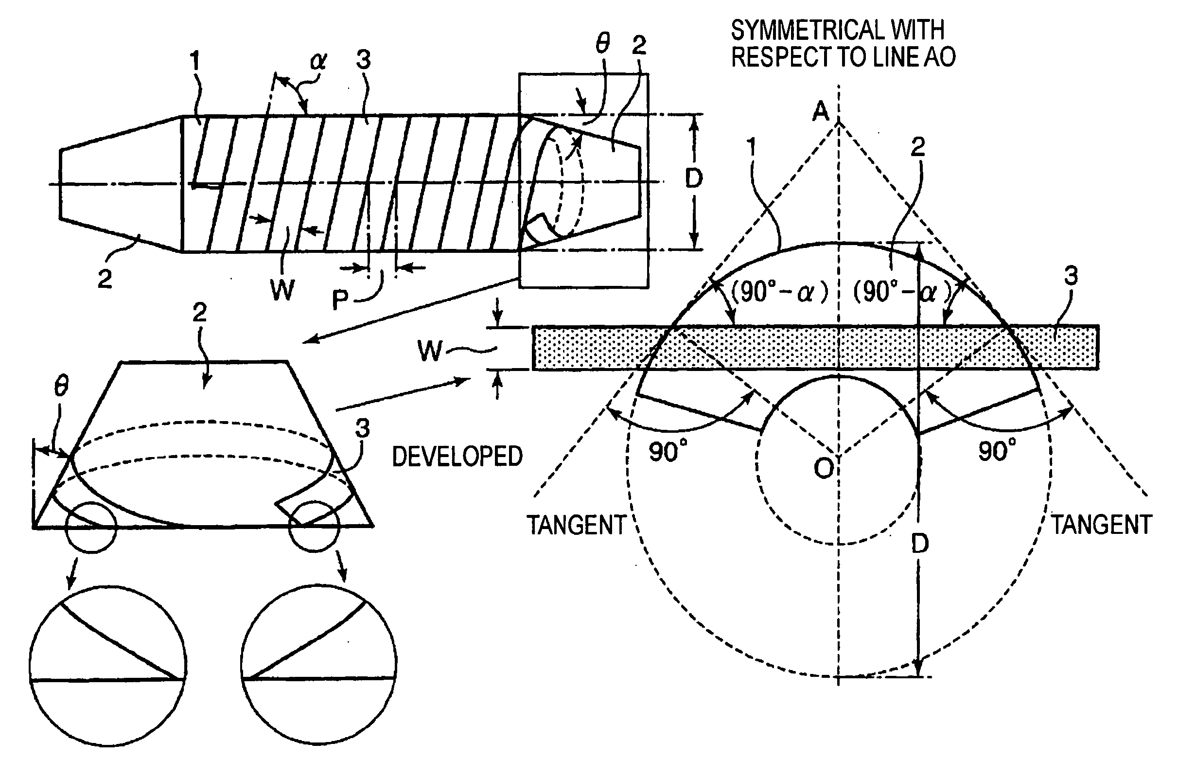
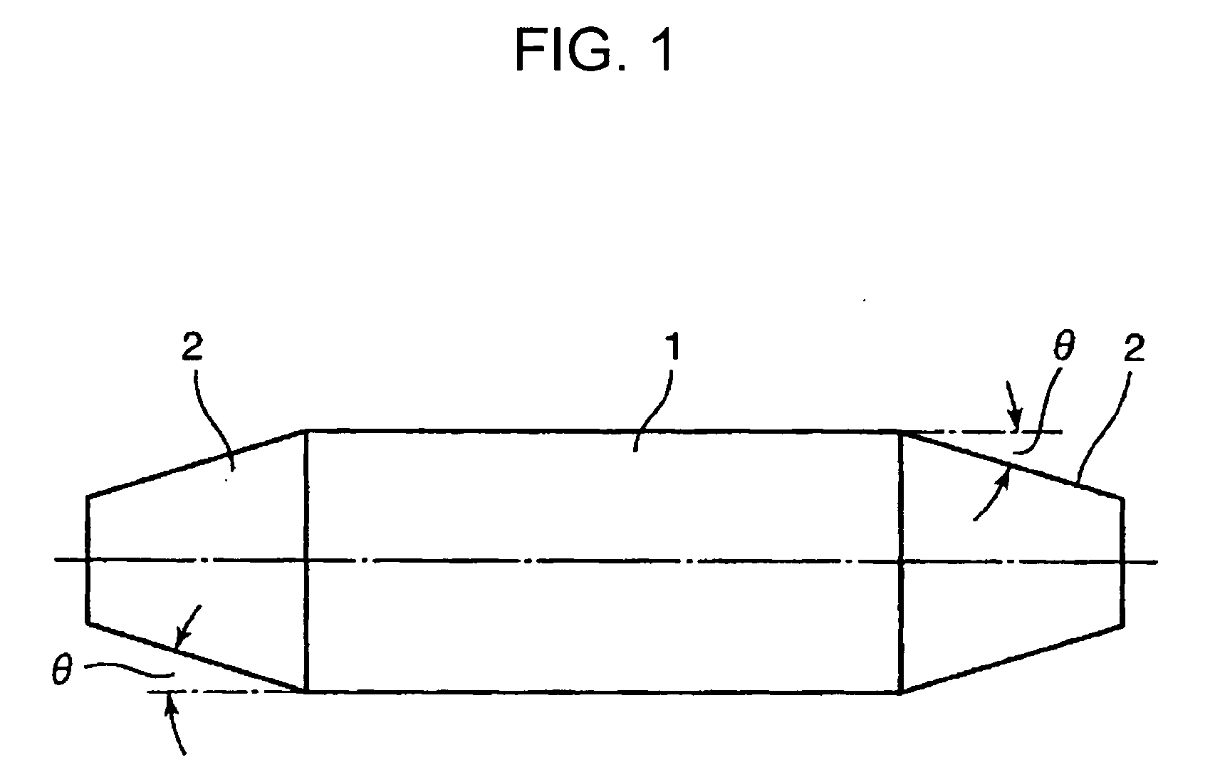
[0044] A tape wire having a width W of 10 mm and a thickness t of 0.2 mm shown in FIG. 8 was closely and solenoidally wound around a bobbin having an outside diameter D of a cylindrical portion of 80 mm, a length L of 500 mm, and a taper angle θ of 30° at a helical winding angle α of 88° so that adjoining turns of the wire did not overlap with each other. The wire was wound from an end of the cylindrical portion to a tapered portion at an angle of 88° to form a first layer, and was wound back in tight contact with the tapered portion. The tape was then wound around the cylindrical portion at 88° in a direction opposite to that for the first layer, thereby forming a second layer. Consequently, the wire could be smoothly wound back to form the second layer while being in tight contact with the tapered portion.

second example

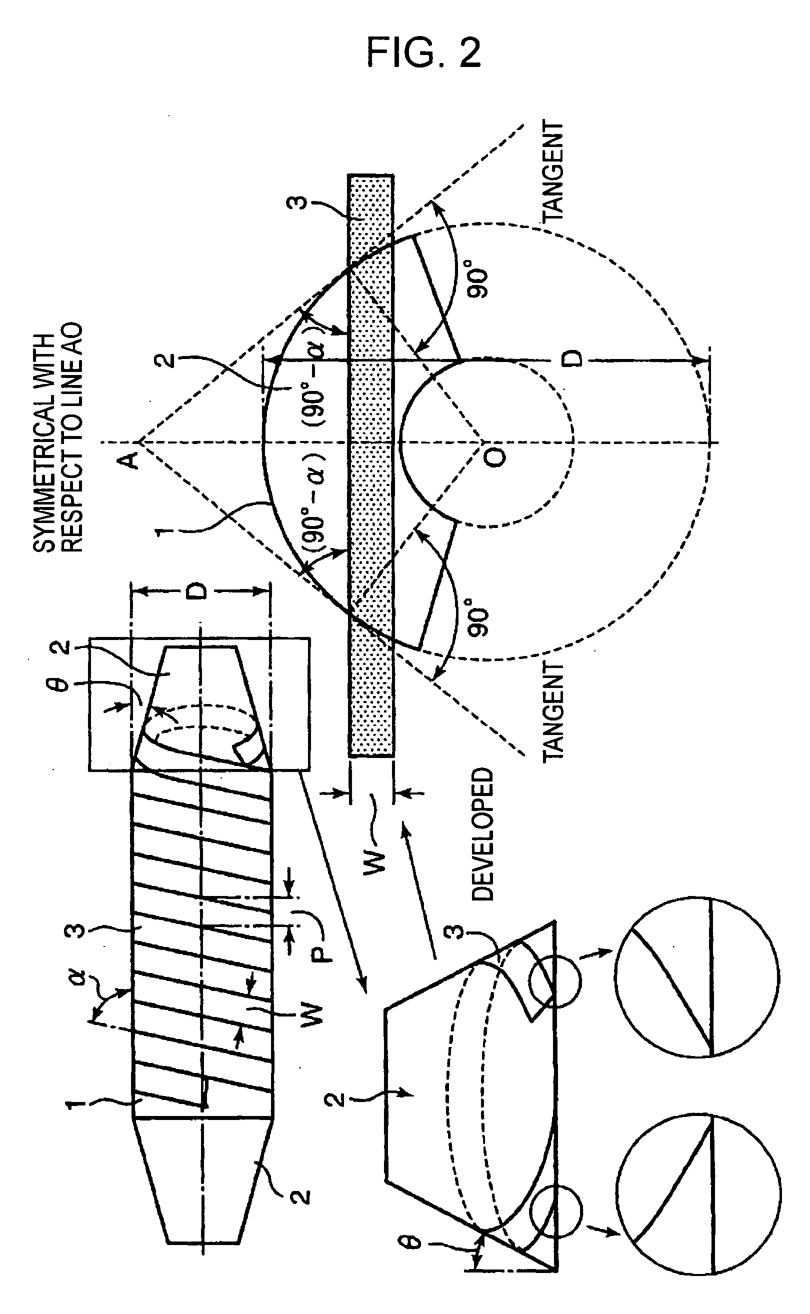
[0045] A tape wire having a width W of 10 mm and a thickness t of 0.2 mm shown in FIG. 10 was closely and solenoidally wound around a bobbin having an outside diameter D of a cylindrical portion of 80 mm, a length L of 500 mm, a taper angle θ1 of 10°, and a taper angle θ2 of 30° at a helical winding angle α of 88° so that adjoining turns of the wire did not overlap with each other. The wire was wound from an end of the cylindrical portion to a first tapered portion at an angle of 88° to form a first layer, was wound back in tight contact with the first tapered portion and a second tapered portion, and was then wound around the cylindrical portion at 88° in a direction opposite to that for the first layer, thereby forming a second layer. Consequently, the wire could be smoothly wound back in tight contact with the tapered portions to form the second layer.

[0046] When the wire is solenoidally wound in multiple layers, the coil diameter gradually increases, and the winding angle with ...


PUM


Abstract

A bobbin for a superconducting coil includes a cylindrical drum, and a tapered portion extending from each end of the drum. A superconducting wire or a precursor of the superconducting wire shaped like a tape is helically wound around the drum in multiple layers. The tapered portion has a tapered surface that is inclined at an arbitrary angle.

Description

BACKGROUND OF THE INVENTION [0001] 1. Field of the Invention [0002] The present invention relates to a bobbin around which a tape-like superconducting wire is helically wound in multiple layers to form a superconducting coil, and to a solenoid coil formed by winding a tape-like superconducting wire around the bobbin in multiple layers. More particularly, the present invention relates to a bobbin that has a cylindrical drum and that allows a tape-like superconducting wire to be helically wound around the bobbin in multiple layers to form a solenoid coil and to be wound back at both ends of the drum by a simple winding operation while minimizing distortion of the wire, and to a solenoid coil formed with the bobbin. [0003] 2. Description of the Related Art [0004] As superconducting wires, a metal superconducting wire of, for example, NbTi or Nb3Sn and an oxide superconducting wire of, for example, bismuth oxide and yttrium oxide are known. The former metal superconducting wire is shape...

Claims


Application Information

Patent Timeline
IPC IPC(8): H01F6/00
CPCG01R33/3815H01F5/02H01F41/0687H01F27/2847H01F6/06H01F41/098
Inventor ZAITSU, KYOJIMIYATAKE, TAKAYUKIMIYAZAKI, TAKAYOSHIOZAKI, OSAMUFUKUYAMA, KAZUHIRO
Owner KOBE STEEL LTD
Why Eureka
Try Eureka