Deposition device
a technology of evaporation device and crucible, which is applied in the direction of vacuum evaporation coating, chemical vapor deposition coating, coating, etc., can solve the problems of limiting the amount of evaporation material which can be filled to an evaporation source, limiting the size of crucible, and increasing the difficulty of continuously processing multiple large-sized substrates. achieve the effect of improving the throughpu
- Summary
- Abstract
- Description
- Claims
- Application Information
AI Technical Summary
Benefits of technology
Problems solved by technology
Method used
Image
Examples
embodiment mode 1
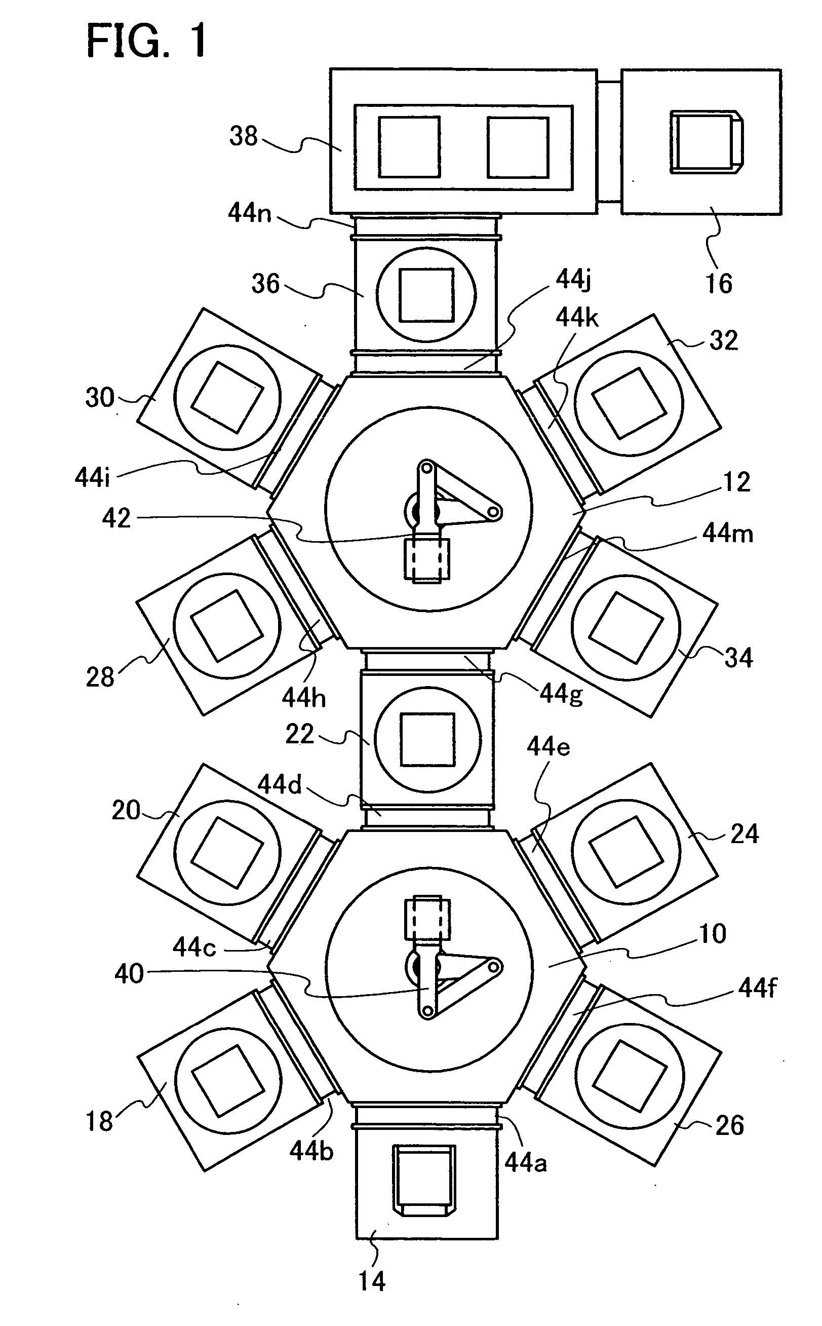
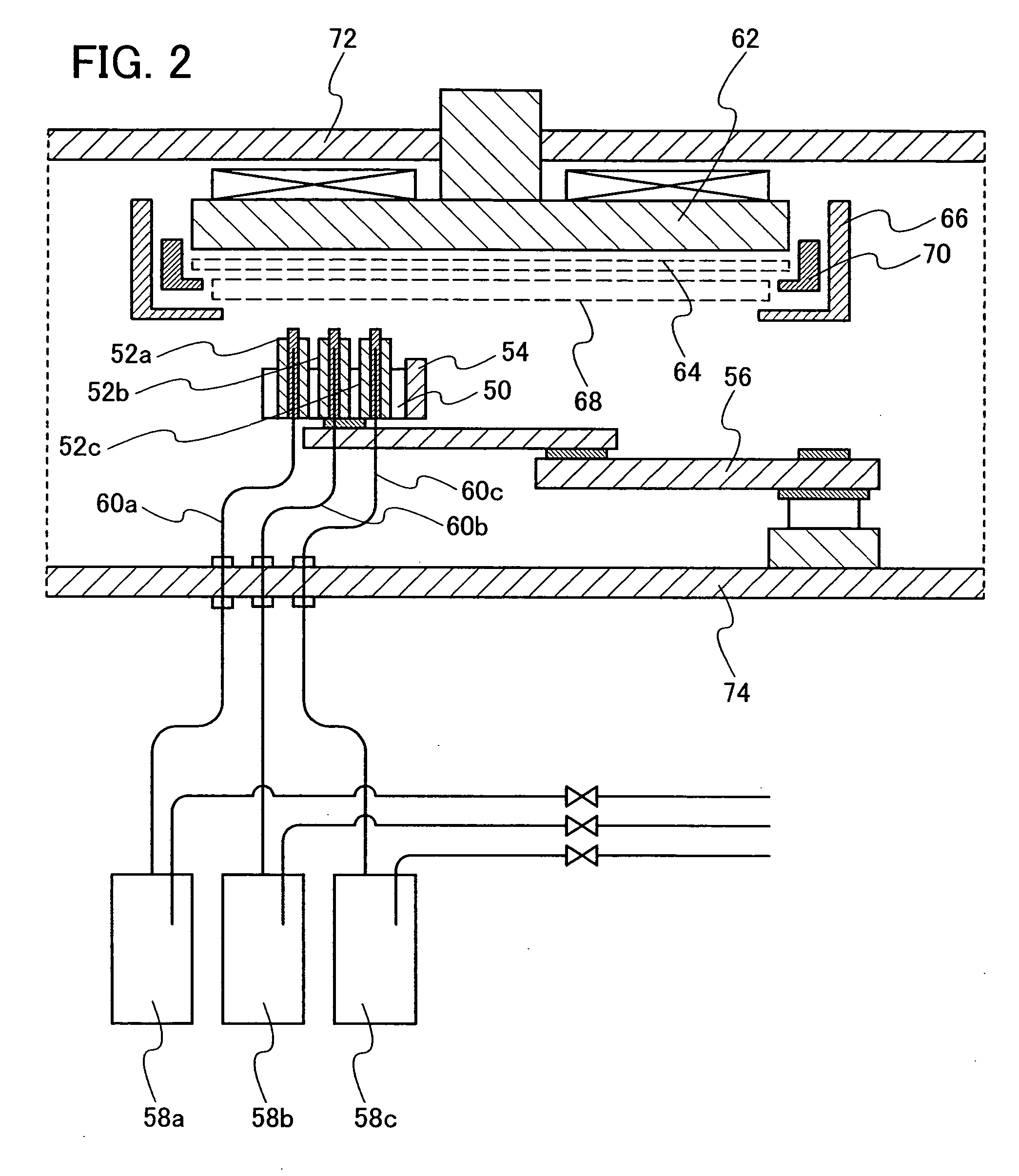
[0060] In this embodiment mode, a structure of a deposition device provided with a scanning evaporation source and an evaporation material supply means connected to the scanning evaporation source will be explained with reference to FIGS. 1 and 2.
[0061]FIG. 1 shows a structure of a deposition device for forming an EL layer over a substrate. It is to be noted that an EL layer refers to a layer at least partially containing a material exhibiting electroluminescence (electroluminescence refers to a phenomenon in which light is emitted when an electric field is applied to a fluorescent material or a phosphorescent material). The EL layer may be formed of a plurality of layers each having a different function. For example, there is a case where a plurality of layers each having a different function such as a hole injecting / transporting layer, a light-emitting layer, or an electron injecting / transporting layer is contained in the EL layer.
[0062] This deposition device includes transfer ...
embodiment mode 2
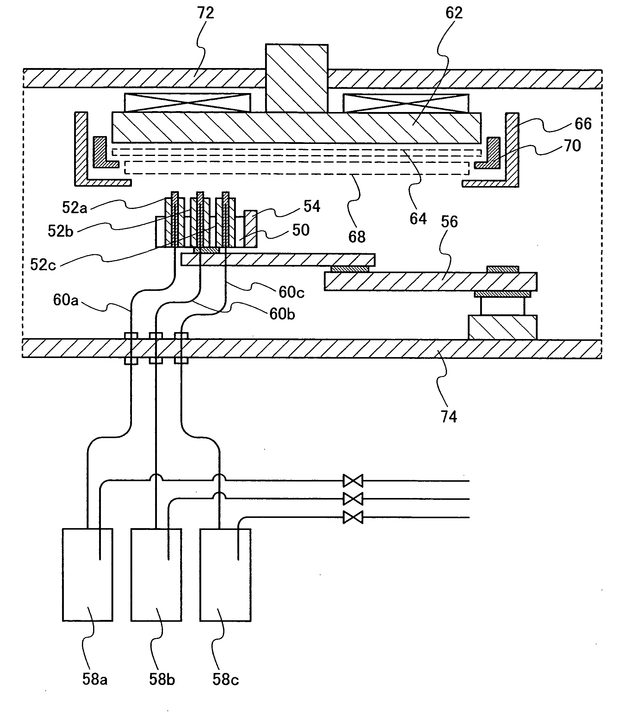
[0082] In this embodiment mode, a structure of a deposition treatment chamber where evaporation is performed by fixing an evaporation source and moving a substrate will be explained with reference to FIG. 3.
[0083]FIG. 3 shows an internal structure of the deposition treatment chamber. The deposition treatment chamber is constructed so that a reduced pressure state can be kept. A jig or the like for fixing an evaporation source or a substrate is provided in an interior side interposed between a top plate 72 and a bottom plate 74 that are included in the deposition treatment chamber.
[0084] Evaporation sources 52a, 52b and 52c provided inside the deposition treatment chamber are the same as the one in Embodiment Mode 1. One or a plurality of evaporation sources can be provided. The evaporation sources 52a, 52b and 52c are attached to an evaporation source holder 50 which is provided on the bottom plate 74 side. Even in a case of fixing a position of the evaporation source 52, a distan...
embodiment mode 3
[0088] In this embodiment mode, a structure of a deposition treatment chamber in which evaporation is performed by moving both an evaporation source and a substrate will be explained with reference to FIGS. 4 and 5. It is to be noted that FIG. 4 is a front view of a deposition treatment chamber and FIG. 5 is a detail view showing an internal structure of the deposition treatment chamber. The following explanation will be made with reference to both of the drawings.
[0089] In FIG. 4, a gate valve 92 is fixed to a deposition treatment chamber 89. A substrate 64 fixed to a transfer table 81 by a chuck 70 is inserted from the gate valve 92, and deposition is performed in a step where the substrate 64 moves inside the deposition treatment chamber 89 on the guide rail 90. By connecting a plurality of such deposition treatment chambers 89 in series, an inline deposition device for forming a plurality of layers of a film can be formed.
[0090] In an internal structure shown in FIG. 5, evapor...
PUM
| Property | Measurement | Unit |
|---|---|---|
| distance | aaaaa | aaaaa |
| size | aaaaa | aaaaa |
| size | aaaaa | aaaaa |
Abstract
Description
Claims
Application Information
 - R&D
- Intellectual Property
- Life Sciences
- Materials
- Tech Scout
- Unparalleled Data Quality
- Higher Quality Content
- 60% Fewer Hallucinations
Browse by: Latest US Patents, China's latest patents, Technical Efficacy Thesaurus, Application Domain, Technology Topic, Popular Technical Reports.
© 2025 PatSnap. All rights reserved.Legal|Privacy policy|Modern Slavery Act Transparency Statement|Sitemap|About US| Contact US: help@patsnap.com


