Eureka AIR delivers breakthrough ideas for toughest innovation challenges, trusted by R&D personnel around the world.

Automatic central buffer coupling with signal transmission device

Inactive Publication Date: 2007-03-08
VOITH TURBO SCHARFENBERG
View PDF4 Cites 12 Cited by
  • Summary
  • Abstract
  • Description
  • Claims
  • Application Information

AI Technical Summary

Benefits of technology

[0015] The solution according to the invention provides a great number of substantial advantages over the central buffer couplings known in the prior art and described above.
[0043] A particularly preferred realization of the central buffer coupling according to the invention provides for using a WLAN signal transmission system as the signal transmitting device. Providing this type of WLAN transmission path between the coupling element and the counter-coupling element of the signal transmitting device allows a data connection at a gross bandwidth of up to 11 Mbit / s to be realized at minimum fluctuation in receiving field strength due to the near-field coupling. Of course, other standards in order to achieve higher gross bandwidths are also conceivable. The desired near-field coupling at the same time solves the main problem of utilizing WLAN, that being the dependency of a given bandwidth on the distance between communication partners. For this reason, using a WLAN signal transmitting device in the inventive solution is of advantage.

Problems solved by technology

The fundamental problem with such known systems for transmitting discrete control signals and data signals is the strong mechanical load brought to bear on the electrical contacts used, in particular while coupling.
Due to the coupling procedures, which are usually automated, but also due to vibrations and attrition during operation as well as atmospheric effects, conventional signal transmission systems normally used in couplings suffer progressive contact damage.
Especially the contact terminals are subject to a considerable degree of wear and corrosion.
Among other things, one consequence of this is that the electrical resistance of the electric contacts increases during signal transmission which impairs the quality of the signals to be transmitted and in extreme cases can even lead to the complete loss of the signal connection.
While such a solution allows for a lesser total outlay of the wiring necessary for an individual electrical contact coupling such that the electrical contact coupling itself can also be configured smaller if need be, it does not eliminate the fundamental problem of the extreme mechanical load brought to bear on the electrical contacts used as arises during the coupling procedure.
Here as well, the electrical contacts are subject to major mechanical load and attrition, especially while being coupled.
The disadvantage to this known solution, however, is especially seen as being the low quality to the data transmission.
In particular, a patch antenna as the conventional solution suggests is only conditionally suited to non-contact data transmission in an automatic central buffer coupling since the total attenuation of the signal transmission system is relatively high.
Yet due to the patch antenna's unfavorable radiation pattern, a relatively high transmission level leads to high antenna member interference emissions.
A further disadvantage to the known solution of the prior art is seen in the fact that the patch antennas' immunity to noise; i.e., the irradiation pattern of external background radiation, is also inadequate in the proposed patch antenna configuration.
In practical use, such circumstances with this type of signal transmission system can at times only dictate an unreliable and interference-prone data transmission.

Method used


Image

  • Automatic central buffer coupling with signal transmission device
  • Automatic central buffer coupling with signal transmission device
  • Automatic central buffer coupling with signal transmission device

Examples


Embodiment Construction

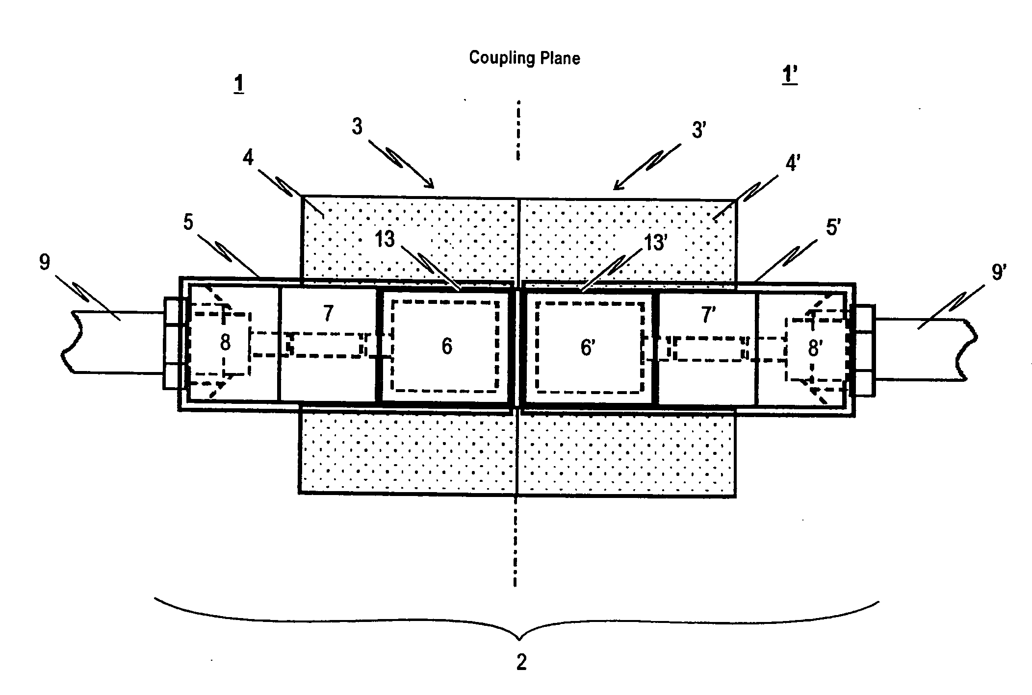
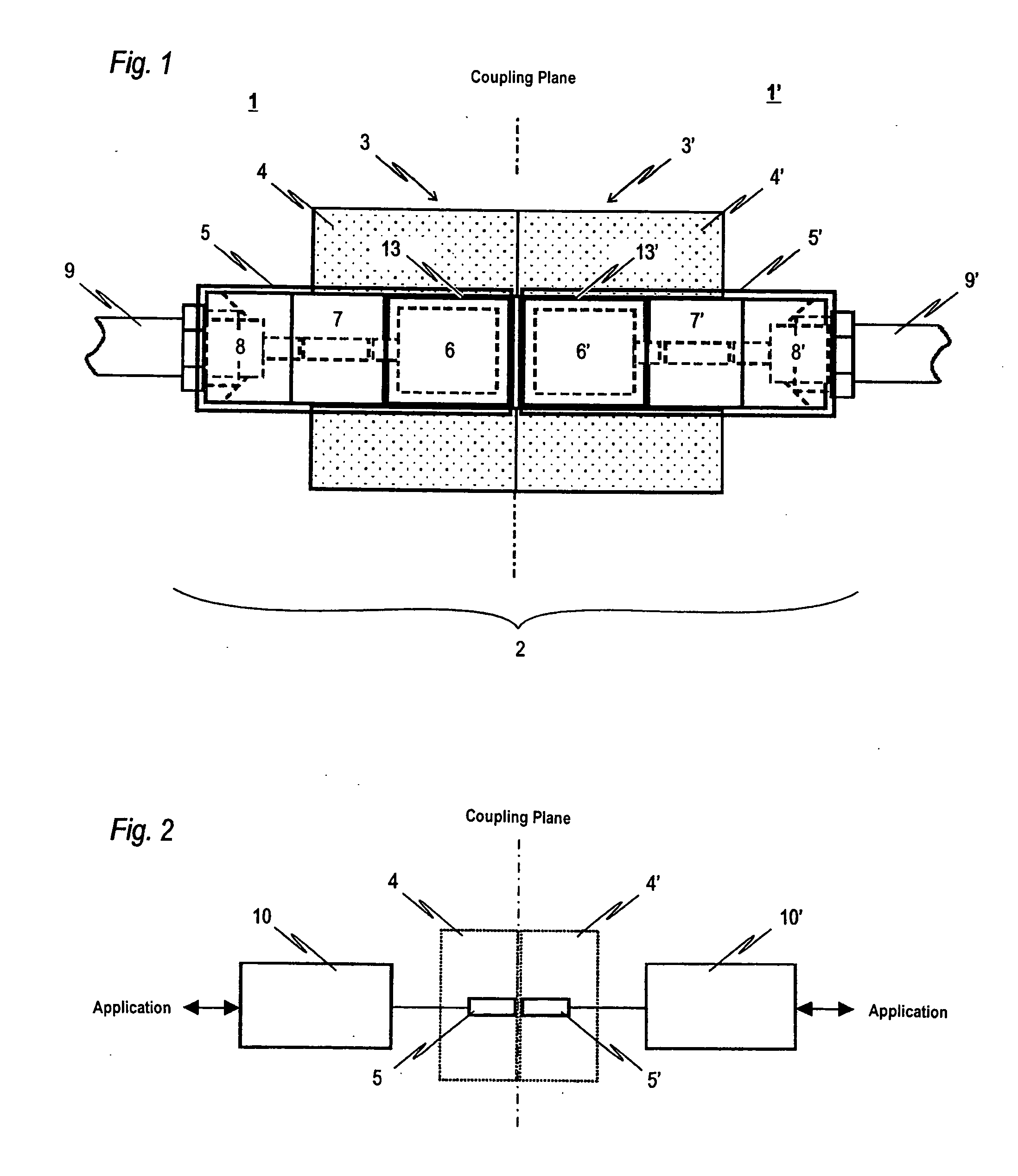
[0053]FIG. 1 is a schematic representation of one possible embodiment of the central buffer coupling 1 according to the invention which integrates a signal transmission device 2. Specifically, FIG. 1 shows a cutaway view of the signal transmission device 2 integrated in a coupled central buffer coupling 1.

[0054] The central buffer coupling 1 depicted in FIG. 1 consists of a (not explicitly shown) coupling head 3 which is coupled in the depicted state with the (likewise not explicitly shown) coupling head 3′ of a counter-coupling 1′. Both coupling heads 3, 3′ have a contact plate 4, 4′, their respective faces abutting in the coupling plane in the coupled state. The signal transmission device 2 is integrated into contact plate 4 of coupling head 3 of coupling 1 and into contact plate 4′ of coupling head 3′ of counter-coupling 1′.

[0055] The signal transmission device 2 exhibits a coupling element 5 and a counter-coupling element 5′, whereby the coupling element 5 is integrated into c...


PUM


Abstract

The present invention relates to an automatic central buffer coupling (1, 1′) for a multi-membered vehicle, in particular a rail-borne vehicle, having a coupling head (3) and a signal transmission device (2) for transmitting electric and / or electronic signals between a first and a second car body. With the objective of integrating a signal transmission device (2) in the central buffer coupling (1) which on the one hand is designed to be rugged and compact and, on the other, is based on a system as free as possible from attrition and maintenance, the present invention provides for the signal transmission device (2) in the central buffer coupling to comprise at least one coupling element (5) and at least one counter-coupling element (5′), wherein the coupling element (5) is integrated in a contact plate (4) of coupling head (3) of coupling (1) and the counter-coupling element (5′) is integrated in a contact plate (4′) of coupling head (3′) of counter-coupling (1′) such that the face side of the coupling element (5) is arranged opposite the face side of the counter-coupling element (5′) integrated in coupling head (3′) of counter-coupling (1′) in the contact plane of coupling heads (3, 3′), and wherein the coupling element (5) and the counter-coupling element (5′) each have an antenna member (6, 6′) comprising a disc monopole antenna (12) configured to transmit data in the GHz frequency range.

Description

CROSS-REFERENCE TO RELATED APPLICATIONS [0001] The present application claims priority to European Patent Office Application No. EP05019569 filed Sep. 8, 2005, and European Patent Office Application No. EP06003184 filed Feb. 16, 2006. TECHNICAL FIELD [0002] The present invention relates to an automatic central buffer coupling for a multi-membered vehicle, in particular a rail-borne vehicle. BACKGROUND OF THE INVENTION [0003] An example of an electric contact coupling for automatic central buffer couplings is known from the EP 0 982 215 B1 printed publication which provides for an electrical cable coupling to be retained in longitudinally-displaceable fashion on a mechanical central buffer coupling. This known cable coupling comprises at least one plug-and-socket connection connected via a connection line arranged on the respective side of a coupling's point of separation for couplable rail vehicles. In order to avoid a redundant contact arrangement disposed symmetrically to the vert...

Claims


Application Information

Patent Timeline
IPC IPC(8): H01R24/00
CPCB61G5/10B61L15/0036H01Q9/40H01Q1/325H01Q1/3233
Inventor PRILL, THOMASKRAUSE, REINERKRAFT, KARL-HEINZ
Owner VOITH TURBO SCHARFENBERG
Why Eureka
Eureka Blog
Learn More