Rotational core biopsy device with liquid cryogen adhesion probe

a cryogen adhesion and biopsy device technology, applied in the field of breast cancer diagnosis and treatment, can solve the problems of difficult needle force into the lesions, device is not designed for resection, tumors are too tough to yield to suction and deformity, etc., to facilitate rapid yet moderate freezing of the target tissue lesion, prevent the destruction of tumor cells, and reduce the effect of seeding

Inactive Publication Date: 2007-03-08
SANARUS TECHNOLOGIES
View PDF25 Cites 173 Cited by
  • Summary
  • Abstract
  • Description
  • Claims
  • Application Information

AI Technical Summary

Benefits of technology

[0008] The device also includes a coring apparatus with structures that permit the surgeon to core a sample of the tumor during the biopsy procedure. The coring apparatus is provided with an outer cutting cannula that advances through a tumor to core a sample of the tumor. The coring apparatus is adapted for use with the probe. The adhesion probe is disposed within the cannula with the distal tip of the probe extending beyond the distal tip of the cannula. The device is inserted into the body until the adhesion probe pierces the tumor. Coolant is directed to the distal tip of the probe to lightly cool the distal tip and the tumor. The lightly cooled distal tip adheres to the tumor cells immediately proximate the distal tip. Once the tumor is secured to the probe, the coring apparatus is actuated to excise tumor tissue surrounding the distal tip. The coring apparatus comprises a cutting cannula and means for rotating and translating the cutting cannula. After coring is complete, the device is removed from the body and the cutting cannula is retracted to release the excised tissue. This method of biopsy prevents ...

Problems solved by technology

It is difficult to force a needle into these lesions because they are resistant to puncture and fairly mobile.
However, the tumor itself must be re-engaged after every coring operation, which entails substantial effort in relocation and confirmation that the target suspect mass has been engaged by the side aperture.
Tumors may be too tough to yield to the suction and deform as necessary to enter the side opening of the cannula.
Indeed, the device is not designed to perform resection with assurance that complete resection of a suspect mass has been accomplished.
Mechanical cutting and disruption of the tissue structure and cancer cell dispersion (that is, tearing of the tissue around the cancer and movement of the cancer cells amongst normal tissue) will result in un...

Method used


Image

  • Rotational core biopsy device with liquid cryogen adhesion probe
  • Rotational core biopsy device with liquid cryogen adhesion probe
  • Rotational core biopsy device with liquid cryogen adhesion probe

Examples


Embodiment Construction

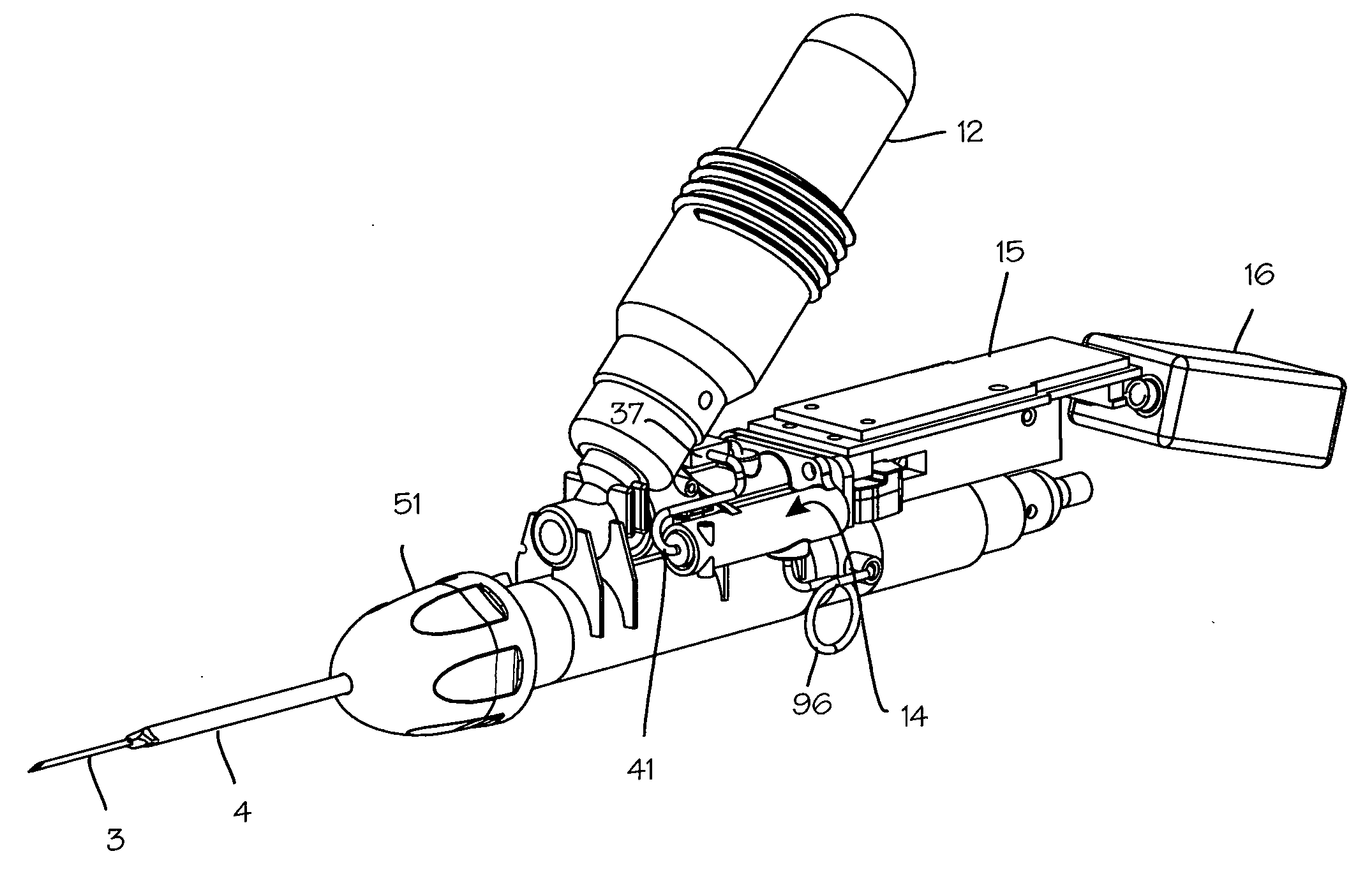
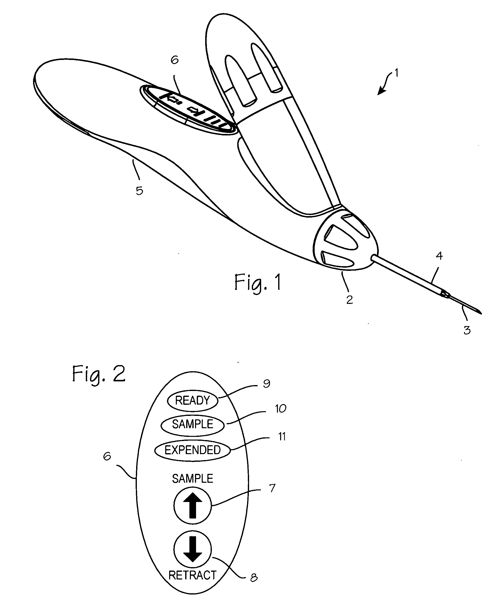
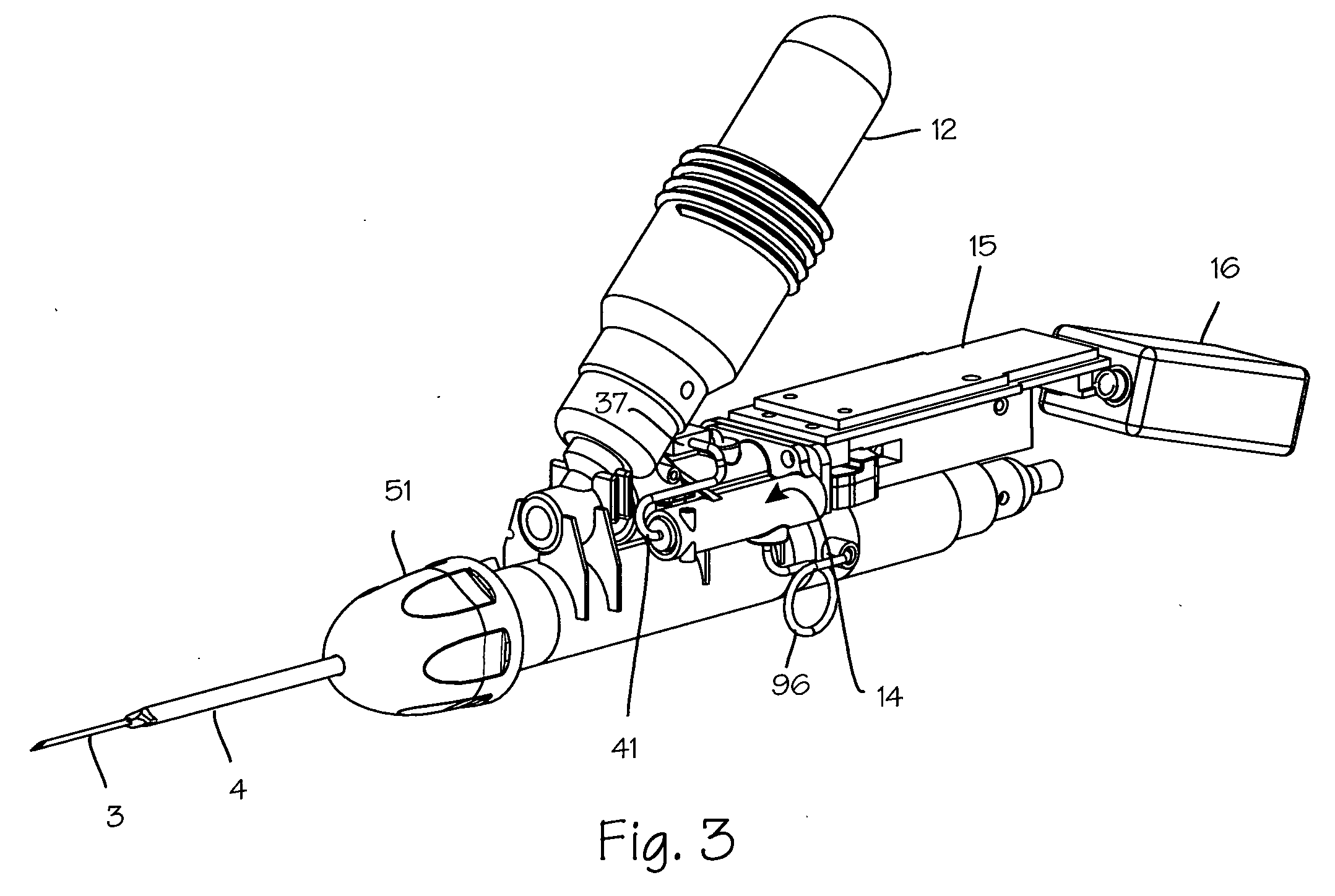
[0025]FIG. 1 illustrates a biopsy instrument 1 which comprises a releasable coring module 2 having an adhesion probe 3 and a cutting cannula 4 and a control housing 5 having a chamber sized and dimensioned to accommodate the releasable coring module. The control housing is further sized and dimensioned to form a convenient handle and to house other components of the biopsy instrument. The housing also comprises a button interface 6, detailed in FIG. 2, which allows the user to control the device and which reports to the user the state of the device. The button interface comprises a sample button 7 which may be depressed by the user to initiate sampling operation of the device, a retract button 8 which may be depressed by the operator to initiate retraction of the cutting cannula after sampling, a ready light 9 which is operable by the device controller to indicate to the operator that the device is ready for use, a sample light 10 which is operable by the control system to indicate ...


PUM


Abstract

A biopsy device comprising a housing and a releasable coring module having an internal needle adapted for securing a suspect mass to the internal needle and an external cutting cannula adapted to slide over the internal needle to cut the suspect mass from any surrounding tissue.

Description

FIELD OF THE INVENTIONS [0001] The devices and methods described below relate to the diagnosis and treatment of breast lesions, and more generally, to the diagnosis and treatment of tumors and lesions throughout the body. BACKGROUND OF THE INVENTIONS [0002] Biopsy is an important procedure used for the diagnosis of patients with cancerous tumors, pre-malignant conditions, and other diseases and disorders. Typically, in the case of cancer, when the physician establishes by means of procedures such as palpation, mammography or x-ray, or ultrasound imaging that suspicious circumstances exist, a biopsy is performed. The biopsy will help determine whether the cells are cancerous, the type of cancer, and what treatment should be used to treat the cancer. Biopsy may be done by an open or percutaneous technique. Open biopsy, which is an invasive surgical procedure using a scalpel and involving direct vision of the target area, removes the entire mass (excisional biopsy) or a part of the mas...

Claims


Application Information

Patent Timeline
IPC IPC(8): A61B10/00A61B18/18A61B17/32A61B17/34
CPCA61B10/0041A61B10/0266A61B10/0275A61B17/32053A61B2010/0208A61B2018/0293A61B2017/00398A61B2017/00734A61B2018/00023A61B2018/0262A61B2017/00199
Inventor DELONZOR, RUSSELL L.SPERO, RICHARD K.OWEN, CHRISTOPHER D.NALIPINSKI, MATTHEW J.DALEO, STEPHEN L.
Owner SANARUS TECHNOLOGIES
Why Eureka
Try Eureka