Paint roller

Inactive Publication Date: 2007-03-15
KURARAY CO LTD +1
View PDF11 Cites 41 Cited by
  • Summary
  • Abstract
  • Description
  • Claims
  • Application Information

AI Technical Summary

Benefits of technology

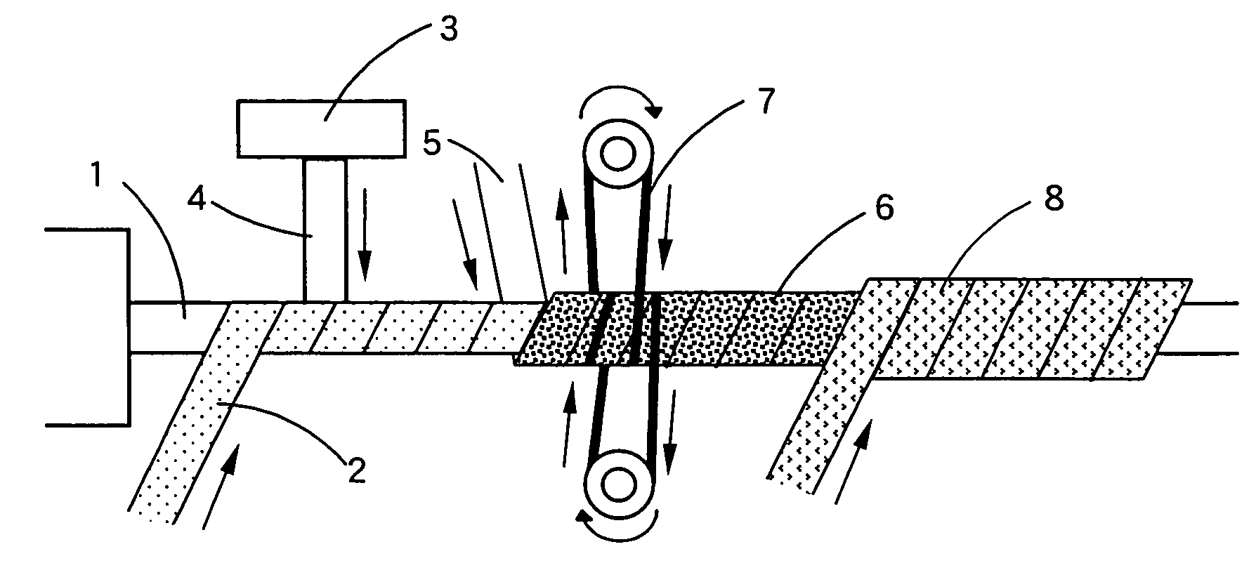
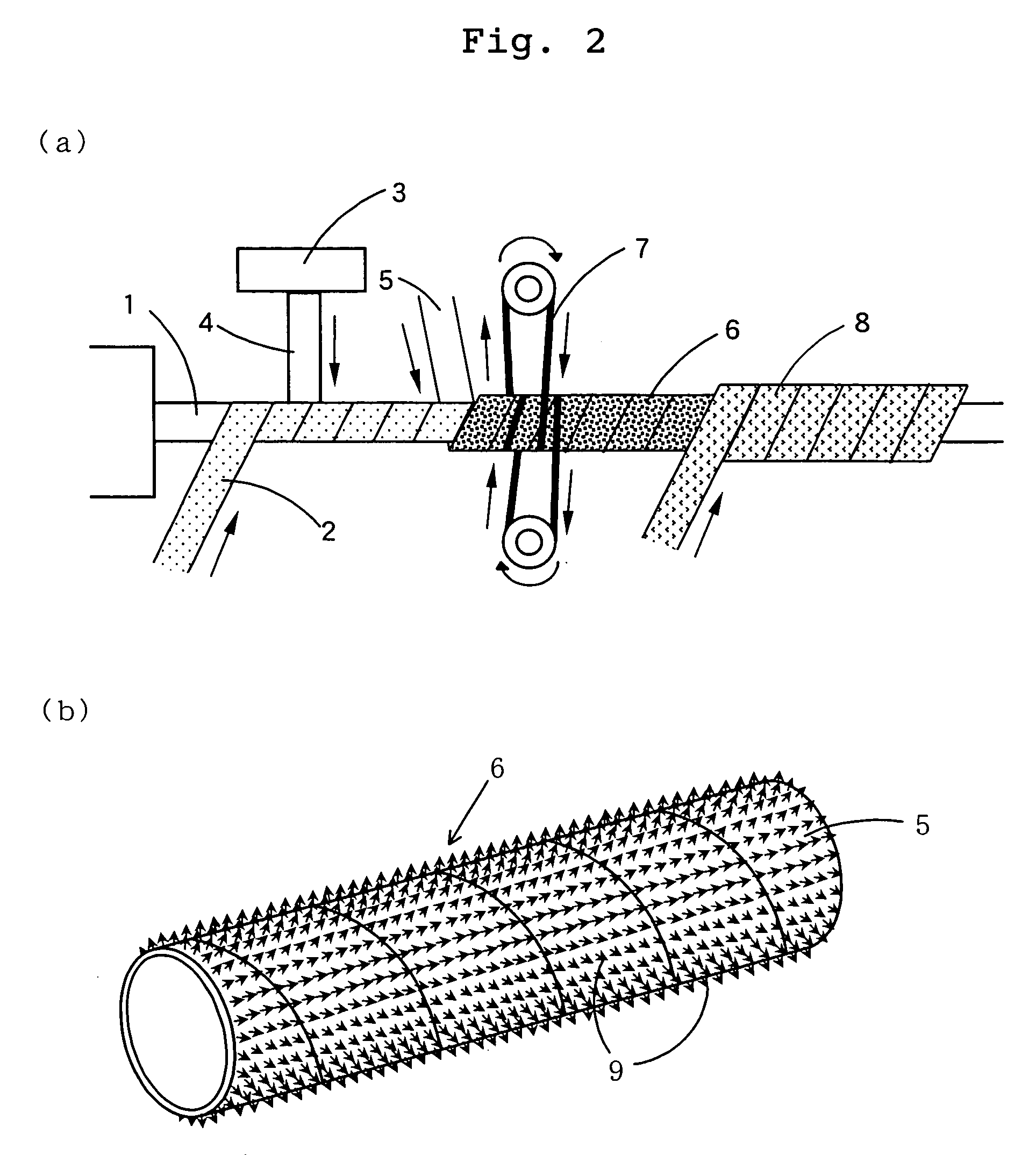
[0022] In the paint roller of the present invention, when an exchange of the cover member is required due to the dirt, damage or wearing of the cover member, the cover member is easily removable from the surface of the tubular core member by hand and the like, and a new cover member can be attached extremely simply and firmly to the core member by an engagement (connection) (e.g., an engagement between the male element on the surface of the tubular core member and the female structure on the inner surface of the cover member). Such that, the tubular core member can be used repeatedly. Moreover, since the mechanism of the engagement is utilized, even if the cover member is not only thick but also porous, the cover member can be exchanged conveniently and efficiently, and the tubular core member is reusable.
[0023] Further, in the paint roller of the present invention, an engagement strength between the male element [e.g., a first (engaging) element having a male structure, which exists on the surface of the tubular core member] and the female element (e.g., a loop on the inner surface of the cover member) can be held in high

Problems solved by technology

Thus, since such a process requires an extremely large number of the steps and is very complex, the production of the paint roller requires much labor and time.
Further, in the case where a solvent-based adhesive is used in the step for winding a cardboard or resin-impregnated paper around a mandrel, or the step for winding a strip-shaped fabric for the cover member around the tubular core member, and the like, the organic solvent in the adhesive causes some problems.
Further, due to the organic solvent, deterioration of the working environment, pollution of natural environment, and the like occur.
Thus, these processes are problematic in an effective utilization of resources, economical efficiency and the like.
However, since a fabric used for a cover member of the paint roller needs to uniformly hold enough amount of a paint upon a painting work operation, the fabric is much thicker than a substrate such as a paper or a resin-impregnated cloth used in a general purpose adhesive tape, and further has a porous structure having many voids throughout fibers thereof.
As a result, the production cost of the cover member having a pressure-sensitive adhesive layer is inevitably greatly increased.
Accordingly, even if the paint roller body is repeatedly reu

Method used


Image

  • Paint roller
  • Paint roller
  • Paint roller

Examples


example 1

[0100] (1) Production of a Loop Thread:

[0101] One nylon filament thread (140 dtex / 14 filaments; manufactured by Toray industries, Inc.) as a sheath thread and one heat-fusing fiber (a sheath-core type conjugated fiber in which the core component comprised a polyethylene terephthalate and the sheath component comprised an ethylene-vinyl alcohol-series copolymer; 165 dtex / 48 filaments) as a core thread was fed to Taslan (a registered trademark of Heberlein Fiber Technology Inc.) nozzle (“#15” manufactured by Heberlein) at a feed rate of the core thread of 1.10 and a feeding rate of the sheath thread of 1.50, and subjected to Taslan process under an air pressure of 540 kPa (5.5 kg / cm2) and a processing speed of 200 m / min. to produce a process thread (loop thread) having 410 dtex / 62 filaments (the average loop number per cm of the thread: 22).

[0102] (2) Production of a Cover Member

[0103] Two polyester filament threads (276 dtex / 48 filaments) were provided for pile threads. One loop t...

example 2

[0110] (1) The same cover member as those obtained in EXAMPLE 1 (2) was adequately cut into a scrollwork pattern and a geometrical pattern to give a plurality of cover member pieces.

[0111] (2) A tubular core member with the male element on a surface thereof was produced by the same step as in EXAMPLE 1 (i), and this preparatory core member was directly cut into length of 23 cm (without attaching the cover member) to produce a tubular core member having the given length (23 cm).

[0112] (3) The plurality of cover member pieces produced in the above (1) were attached to the surface of the tubular core member in length of 23 cm produced in the above (2) at a space from each other, to give a effect roller.

[0113] (4) The painting with the effect roller produced in above (3) achieved that the same pattern design as the pattern on the surface of the effect roller was smoothly painted on a surface to be painted.

example 3

[0114] (1) Production of the Cover Member

[0115] (i) Two polyester filament threads (276 dtex / 48 filaments) were provided for pile threads. Two polyester false-twisted filament thread (220 dtex / 72 filaments) and one heat-fusing fiber filament (filament thread; 165 dtex / 48 filaments; “Sophista” manufactured by Kuraray Co., Ltd.) were used as ground yarns. The above ground yarns were aligned and knitted with a circular knitting machine to give a woven fabric having a pile made of the polyester filament thread on the upper surface (weight of the woven fabric: 540 g / m2, thickness of the woven fabric: 7 mm, pile density on the upper surface: 22 / cm2, and average pile height: 7 mm).

[0116] (ii) With the use of a polyester false-twisted thread (80 dtex / 24 filaments), a tricot fabric (weight of the woven fabric: 150 g / m2, thickness of the woven fabric: 1.5 mm) was produced, then one surface of the tricot fabric was raised with a raising machine to produce a tricot raising fabric.

[0117] (iii...


PUM

PropertyMeasurementUnit
Lengthaaaaaaaaaa
Heightaaaaaaaaaa
Densityaaaaaaaaaa

Abstract

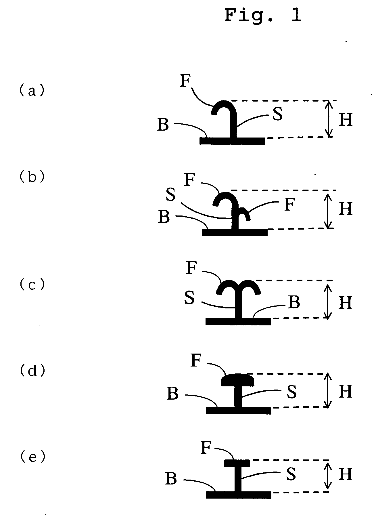
A paint roller comprises a liquid-impermeable tubular core member 6 with an engaging element 9 having a male structure of a separable fastener and a height of 0.3 to 4.0 mm on a surface thereof, and a cover member 8 with a female structure and a loop on the inner surface capable of male-female engaging with the engaging element on the surface of the core member. The density of the engaging element on the surface of the core member is 30 to 150/cm2. Thus, in such paint roller, when the cover member becomes dirty, damaged, or worn, the cover member can be exchanged to a new cover member. Such that, a roller body is repeatedly usable, and the paint roller can provide a good painted surface. Moreover, there is also provided an effect roller in which a painting pattern can be changed optionally.

Description

TECHNICAL FIELD [0001] The present invention relates to a paint roller. More specifically, the present invention relates to a paint roller comprising a tubular core member (tubular core part) and a cover member attached on the surface of the core member. In the paint roller, the cover member is removable from the tubular core member and easily exchangeable for a new cover member, when the cover member becomes dirty, damaged, or worn. In the paint roller of the present invention, the tubular core member is reusable repeatedly. Moreover, the present invention provides a paint roller with which a design (or figure, marking) having a desired pattern, mark and others can be painted on a surface of an object to be painted. Further, in the paint roller, a kind or content of a painting pattern on a surface of an object to be painted is freely changeable according to each aspect. BACKGROUND ART [0002] Conventionally, a paint roller has been produced by spirally (or helically) winding (or wra...

Claims


Application Information

Patent Timeline
IPC IPC(8): B05C17/02A46B7/04A46B3/00A46B3/18A46B7/10A46B13/00D03D1/00D03D15/00D03D27/00
CPCA46B3/18B05C17/0207A46B2200/202A46B13/006
Inventor YAMAGUCHI, TOSIROUOHYAMA, TOSHIKAZU
Owner KURARAY CO LTD
Why Eureka
Try Eureka