
Apparatus and method for monitoring in-transit shipments

a technology for in-transit shipments and apparatus, applied in the field of shipping, can solve the problems of inability to detect damage, lack of accountability for the condition, and the complexity of ensuring the safe delivery of products and goods to their ultimate destination, and achieve the effect of less in-transit damage and shortening holding times

Inactive Publication Date: 2007-03-15
RFID MICRO
View PDF4 Cites 49 Cited by
  • Summary
  • Abstract
  • Description
  • Claims
  • Application Information

AI Technical Summary

Benefits of technology

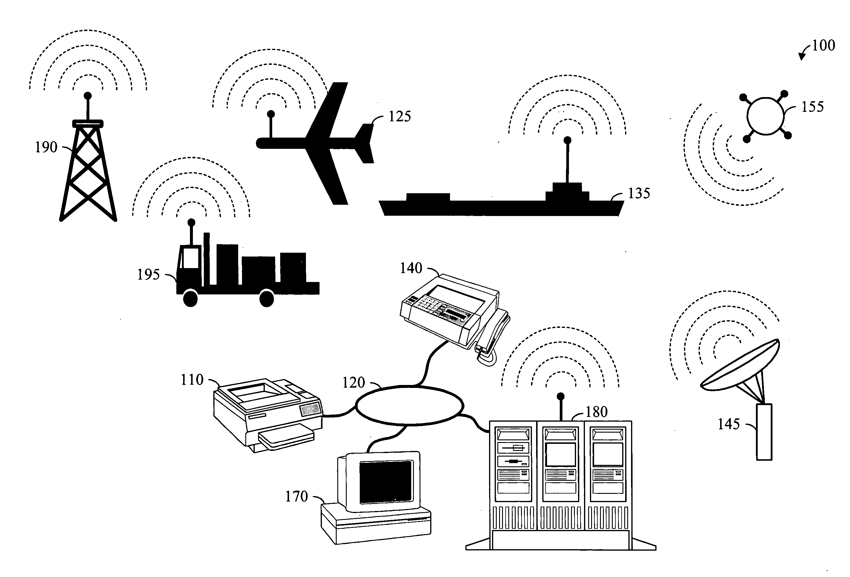
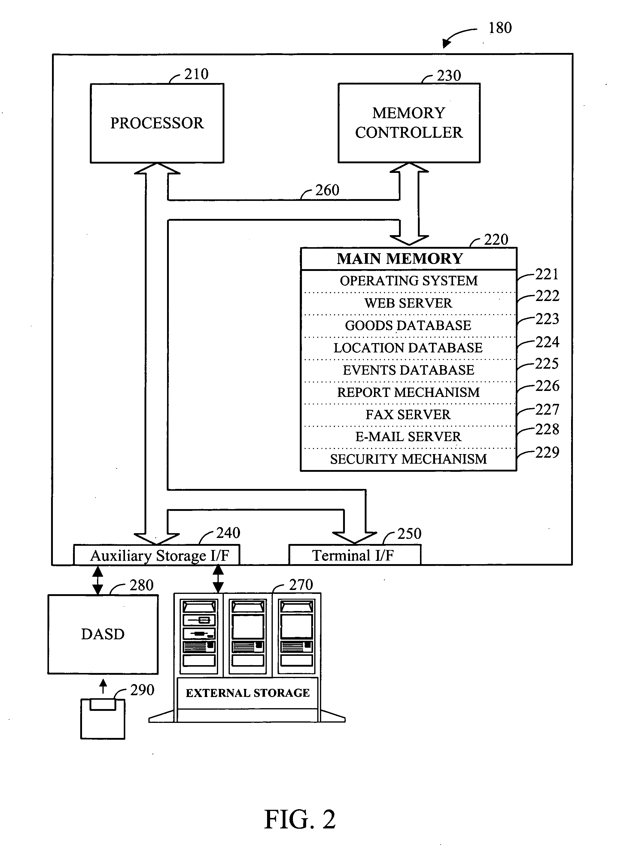
[0012] This “time-location-status” information may be stored locally in conjunction with the in-transit goods and can be accessed in a variety of ways. For example, the in-transit information may be periodically “uploaded” to a more sophisticated computer system at various intervals using standard digital transmission methodologies such as Global Positioning Satellite (GPS) technology. Additionally, a graphical user interface may be provided for inputting, updating, and accessing the in-transit environmental information. The in-transit environmental information may be accumulated and stored in a master database and accessed via the graphical user interface. The interface also provides access to a series of web-based reports that allow various entities to access the environmental information stored in the database, within the permission and privacy constraints of the system. This interface provides valuable information that can be used for a variety of purposes. For example, by tracking the location of a series of shipments over an extended period of time, a historical tracking record can be created. This historical information can be used to project future events that may assist in the streamlining of the shipping process, such as shortening holding times as well as determining the most probable location for damage to occur in the shipping process. By analyzing and acting on this information, future shipments may arrive more quickly and experience less in-transit damage.

Problems solved by technology

In addition to the complications associated with the ever-expanding global distribution system for transporting goods from one location to another, the responsibility for ensuring safe delivery of products and goods to their ultimate destination is becoming more complex.
However, the practical realities associated with this shipping methodology also introduce certain concerns.
One downside of the multiple carrier shipping process is the lack of accountability for the condition of the in-transit goods and products as they are transferred from one carrier to another.
For example, while the goods or products may be damaged in transit with one carrier, the damage may not be detected until the goods or products arrive at their destination, having been transported by a succession of intermediate carriers.
When trying to determine which carrier is responsible for the damage, it may be difficult to ascertain exactly where and when the damage occurred and, correspondingly, if may be difficult to assign responsibility for the damage to the goods or products.
While each carrier may choose to inspect the goods or products upon receipt to verify the presence of lack of damage to the goods or products, this solution is impractical for many reasons.
First, some damage may be hidden and imperceptible until the product is installed and tested at its final location.
Second, the logistics associated with opening a cargo or shipping container to conduct intermediate inspections in transit is time-consuming and labor intensive, adding significant cost to the overall process.
This is an undesirable outcome for all participants in the shipping process.
While the typical piezoelectric sensor may provide certain information, they also have certain limitations.
While this range if very broad, the wide dynamic range makes the sensing of low levels of shock or acceleration very difficult without using expensive 12-bit or better analog to digital converters to record the sensed data.
If a package bearing the sensor is dropped, the 1 G field will be within the parameters of the “noise” of the device and cannot be accurately detected until it hits the floor.
The standard piezoelectric sensor is also very sensitive to air currents that cause rapid temperature changes, possibly resulting in large false G-force readings.
However, even with these manufacturing precautions, the piezoelectric sensor may also produce spurious output with slow changes of temperature, particularly when changing from a cold environment to a hot environment as might happen when a package is moved from a freezer car to a shipping dock in 110° degree weather.
Accordingly, the disadvantages associated with the standard piezoelectric sensor limit the usefulness of the information gathered by the device.

Method used


Image

  • Apparatus and method for monitoring in-transit shipments
  • Apparatus and method for monitoring in-transit shipments
  • Apparatus and method for monitoring in-transit shipments

Examples


Embodiment Construction

[0019] Radio frequency, or RF, refers to that portion of the electromagnetic spectrum in which electromagnetic waves can be generated by alternating current fed to an antenna. One very popular RF standard is known as “bluetooth.” Bluetooth is an industrial specification commonly used to implement wireless personal area networks (PANs). Bluetooth communication provides a way to connect and exchange information between devices like personal digital assistants (PDAs), mobile phones, laptops, PCs, printers and digital cameras via a secure, low-cost, globally available short-range radio frequency. Bluetooth lets these devices talk to each other when they come in range, even if they are not in the same room, as long as they are within up to 100 meters (328 feet) of each other, dependent on the power class of the product. Bluetooth is defined in IEEE standard 802.15.1.

[0020] The effective transmission range for standard Bluetooth wireless communication is about 10 meters. With optional po...


PUM


Abstract

By employing a one or more sensors or monitors, environmental conditions and exceptions noted during the shipment of the goods and products can be monitored, stored, and eventually reported. The information about the in-transit goods and products being tracked may also be collected and transmitted by one or more wireless communication devices such as radios, transceivers, and Global Positioning System (GPS) satellites in conjunction with RF communication and / or RFID technology. Once collected, the environmental condition data may be used to assign liability for any damage that occurred to the in-transit goods and products.

Description

BACKGROUND OF THE INVENTION [0001] 1. Field of the Invention [0002] The present invention relates generally to the field of shipping and more particularly to the use of computer-based systems and methods for tracking and monitoring the status of in-transit goods. [0003] 2. Background Art [0004] In the shipping business, products and goods may be transported by a wide variety of shipping vehicles and methods. For example, it's not unusual for an item to be transported from the place of manufacture to the place of use by one or more of the following: train, boat, airplane, truck, etc. In addition to the complications associated with the ever-expanding global distribution system for transporting goods from one location to another, the responsibility for ensuring safe delivery of products and goods to their ultimate destination is becoming more complex. This is especially true with the increasingly diverse number of carriers in the marketplace. For example, a product may be manufactured...

Claims


Application Information

Patent Timeline
Patent Type & Authority Applications(United States)
IPC IPC(8): G01P15/08H04Q7/00
CPCG01P1/127
Inventor GRIFFIN, JIMPENCE, STEVEJACKSON, ROGERHALLOCK, NICK
Owner RFID MICRO
Learn More