Fabricated rotor assembly fixture and method

a technology of rotors and fixtures, applied in the direction of synchronous motors, magnetic circuit rotating parts, magnetic circuit shape/form/construction, etc., can solve the problems of premature failure of end rings, lessening performance, and failure of motors, so as to improve rotor performance and construction

Inactive Publication Date: 2007-03-22
RELIANCE ELECTRIC TECH
View PDF45 Cites 16 Cited by
  • Summary
  • Abstract
  • Description
  • Claims
  • Application Information

AI Technical Summary

Benefits of technology

[0009] In accordance with one embodiment, the present technique provides an apparatus for assembling a rotor. The exemplary apparatus includes a base that has a central aperture and a seating surface for receiving the rotor. An arbor then extends through the central aperture, the arbor having a longitudinal axis that is substantially orthogonal to the seating surface, and including threaded ends opposite with respect to one another. The exemplary apparatus also includes at least one member of a family of fixtures coupleable to the arbo

Problems solved by technology

For example, if not properly accounted for, the centripetal and centrifugal forces developed in the end ring may cause the end ring to prematurely malfunction.
Moreover, these centripetal and centrifugal forces may, overtime, negatively affect the mechanical integrity of the rotor, leading to a lessening of performance and, in certain instances, failure of the motor.
Undeniably, loss of performance and motor failure are events that can lead to unwanted costs and delays.
Unfortunately, heat generated during a brazing process can negatively affect the material of the end rings and/or the conductor.
In turn, such annealing reduces the yield strength of the annealed materi

Method used


Image

  • Fabricated rotor assembly fixture and method
  • Fabricated rotor assembly fixture and method
  • Fabricated rotor assembly fixture and method

Examples


Embodiment Construction

[0021] As discussed in detail below, embodiments of the present technique provide apparatus and methods related to the manufacture of rotors for induction devices. Although the following discussion focuses on induction motors and generators, the present technique also affords benefits to a number of applications in which rotor integrity and design is a concern. Accordingly, the following discussion provides exemplary embodiments of the present technique and, as such, should not be viewed as limiting the appended claims to the embodiments described.

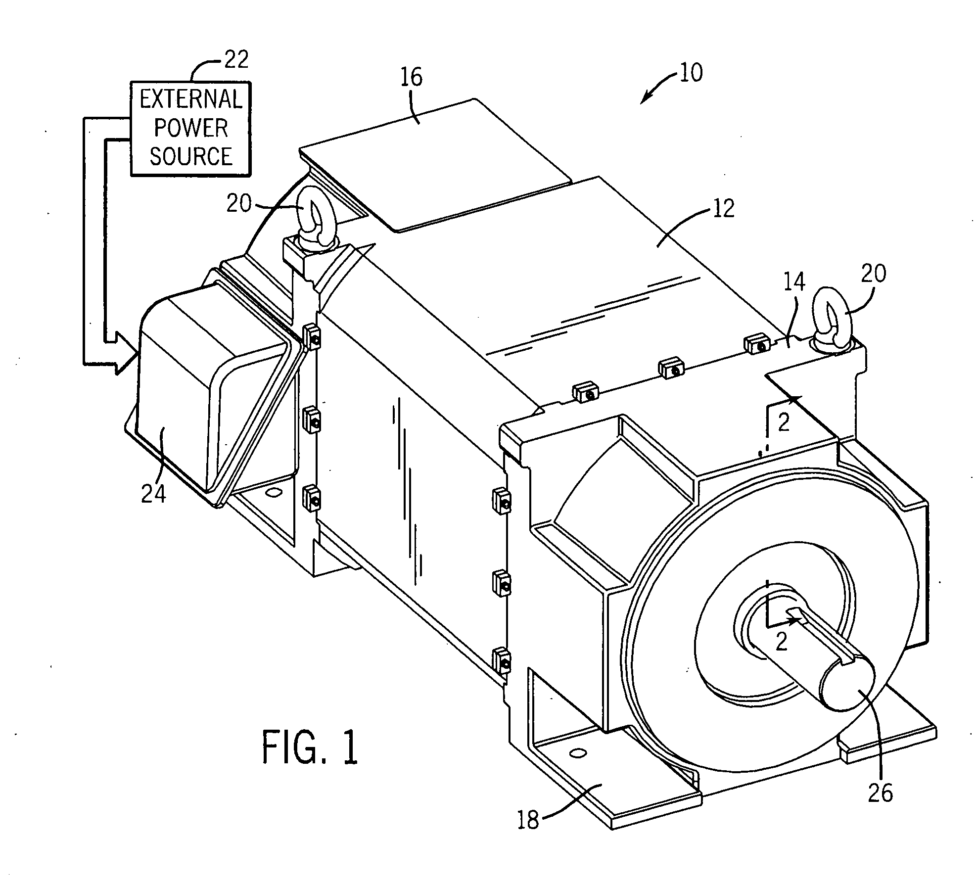
[0022] Turning to the drawings, FIG. 1 illustrates an exemplary electric motor 10. The exemplary motor 10 is an induction motor housed in a motor housing and includes a frame 12 capped at each end by end caps 14 and 16, respectively. The frame 12 and the end caps 14 and 16 may be formed of various materials, such as cast iron, steel, aluminum or any other suitable structural material. Advantageously, the end caps 14 and 16 may include mou...


PUM

PropertyMeasurementUnit
Lengthaaaaaaaaaa
Forceaaaaaaaaaa
Diameteraaaaaaaaaa

Abstract

In accordance with one embodiment, the present technique provides an apparatus for assembling a rotor. The exemplary apparatus includes a base that has a central aperture and a seating surface for receiving the rotor. An arbor then extends through the central aperture, the arbor having a longitudinal axis that is substantially orthogonal to the seating surface, and including threaded ends opposite with respect to one another. The exemplary apparatus also includes at least one member of a family of fixtures coupleable to the arbor, the family including a pressure fixture that has first and second piston assemblies disposed at diametrically opposite locations to one another, the family also including a support fixture coupleable the arbor and having members extending axially therefrom, the members being configured to support securing members of the rotor. Advantageously, the exemplary apparatus provides for a mechanism through which a securing member may be symmetrically installed with respect to the rotor core, thus improving rotor performance and construction.

Description

BACKGROUND [0001] The present technique relates generally to the field of electrical machines, and particularly to rotors for induction devices, such as a fabricated squirrel cage rotor, for example. [0002] Electrical machines, such a motors and generators, are commonly found in industrial, commercial, and consumer settings. In industry, such machines are employed to drive various kinds of devices, including pumps, conveyors, compressors, fans, and so forth, to mention only a few, and are employed to generate electrical power. In the case of electric motors and generators, these devices generally include a stator, comprising a multiplicity of stator windings, surrounding a rotor. [0003] By establishing an electromagnetic relationship between the rotor and the stator, electrical energy can be converted into kinetic energy, and vice-versa. In the case of alternating current (ac) motors, ac power applied to the stator windings effectuates rotation of the rotor. The speed of this rotati...

Claims


Application Information

Patent Timeline
IPC IPC(8): H02K17/00H02K15/00
CPCH02K15/0012H02K17/165Y10T29/49011Y10T29/49009Y10T29/53143Y10T29/49012
Inventor PIZZICHIL, WILLIAM P.
Owner RELIANCE ELECTRIC TECH
Why Eureka
Try Eureka