Heat exchanger

a heat exchanger and heat exchanger technology, applied in the field of fluid cooling pipes, can solve the problems of difficult placement of the body to the underfloor or the back surface of the apparatus, time-consuming, and bulky body, and achieve the effects of improving durability, easy manufacturing of products, and easy manufacturing

Active Publication Date: 2007-03-22
USUI KOKUSAI SANGYO KAISHA LTD
View PDF10 Cites 25 Cited by
  • Summary
  • Abstract
  • Description
  • Claims
  • Application Information

AI Technical Summary

Benefits of technology

[0033] The present invention has such a structure as described above that the opposing end surfaces of the fin member include the concave shaped engagement grooves which engage with the straight pipe sections of meandering pipe main body to form heat exchanger, so that comparing to the conventional technique in which a pipe main body is inserted into breakthroughs of a fin member, a heat exchanger according to the present invention is easy to manufacture as well as fin member thereof is less subjected to damages. As such, the durability of products improves and easy manufacturing thereof is achieved. Further, simplification of manufacturing technique and manufacturing steps can minimize manufacturing cost, thereby realizing to produce inexpensive products. Furtherm

Problems solved by technology

In the pipe main body as disclosed in Japanese Patent Laying-Open Nos. 09-42573 and 2002-364476, however, due to the fin member arranged spirally and radialy, bending into a small curvature radius is difficult and therefore the entire body tends to be bulky and furthermore it is difficult to place the body to the underfloor or to a back surface of an apparatus.
Therefore, such task requires carefulness and is time consuming.
Also, this method in which the pipe main bodies are inserted into the thin plate-like fins involves difficulty in bendin

Method used


Image

  • Heat exchanger
  • Heat exchanger
  • Heat exchanger

Examples


first embodiment

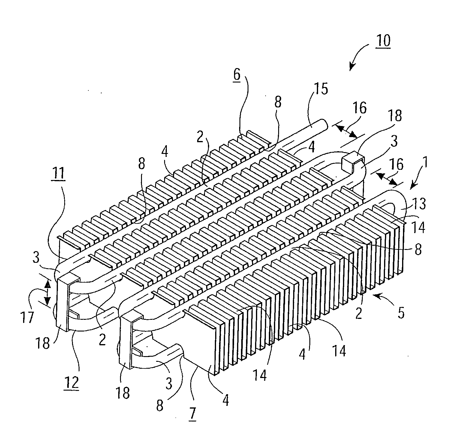
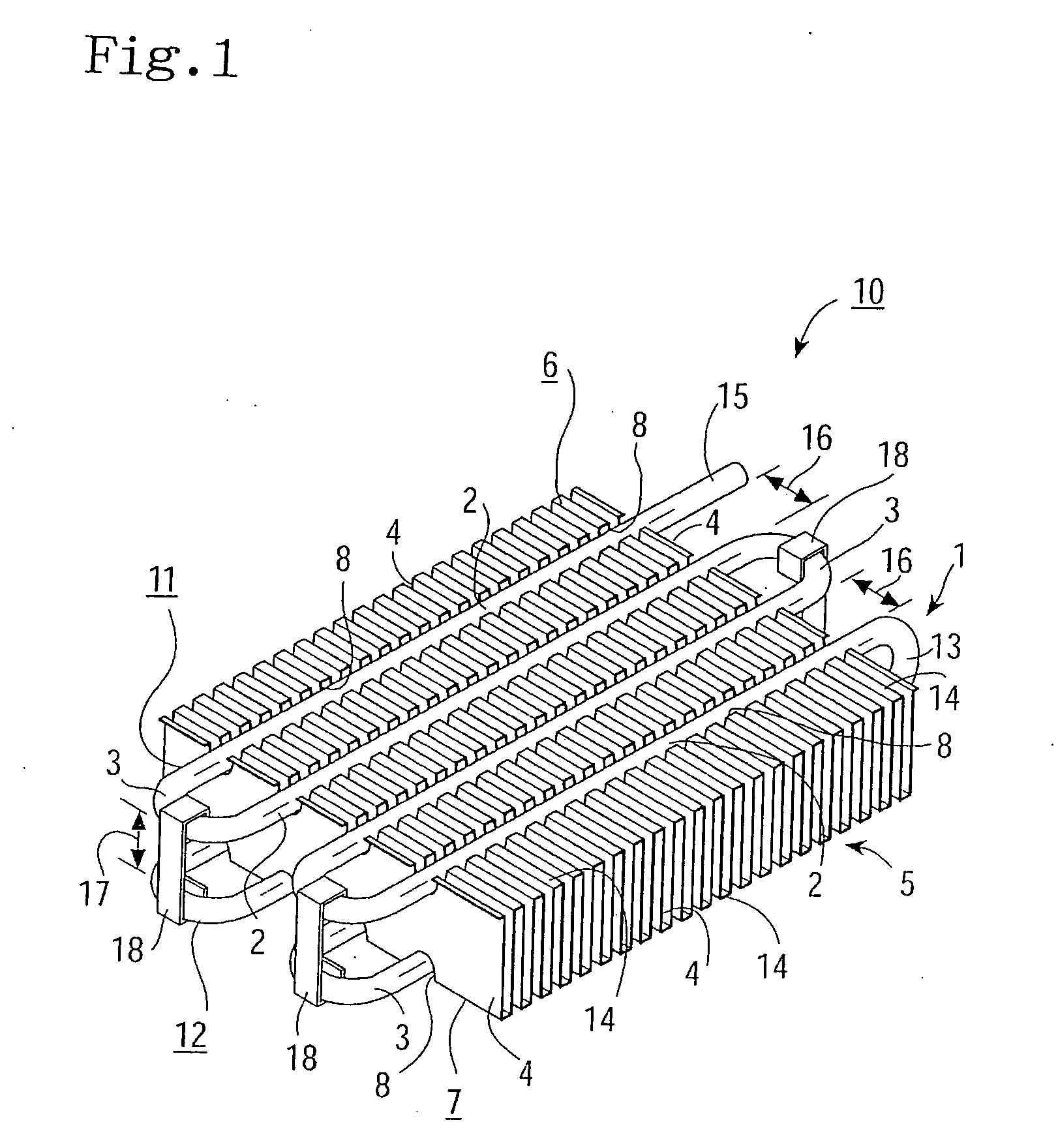
[0068] The first embodiment in which the heat exchanger according to the present invention is exemplified as a fuel pipe to be disposed onto an underfloor of vehicles is hereinafter explained into detail referring to FIGS. 1 to 6. (1) denotes a meandering pipe main body in which a pair of meandering sections (11), (12), composed of a plurality of straight pipe sections (2) arranged in parallel with desired opposing gaps (16) between the straight pipe sections (2) and bend portions (3) for connecting the plurality of straight pipe sections (2), are placed within insertion gap (17) for a fin member so as to be opposed to each other. Within insertion gap (17) formed between the first meandering section (11) and the second meandering section (12), there is placed fin member (5) provided with a plurality of rectangular shaped engagement grooves (8) at constant distances on both end surfaces (6), (7) opposing to each other and composed of a plurality of fins (4) in parallel. Further, stra...

third embodiment

[0088] in such conventional art as taught in Japanese Patent Laying-Open No. 2003-88924 that a mandrel is employed as the expanding means, it is necessary to connect a U-bend pipe to the straight pipe after the straight pipe having been inserted into thin fins, is expanded. To the contrary, in the present invention, meandering pipe main body (1) is inwardly pressurized to expand after disposing straight pipe sections (2) in engagement grooves (8), thereby fitting straight pipe sections (2) with engagement grooves (8) tightly. Therefore, brazing or welding or the like between pipes after the expansion thereof can be omitted, and thus the working efficiency can be improved and the brakeage of fin member (5) or other inadvertent damages are avoidable.

[0089] Straight pipe sections (2) are secured with engagement grooves (8), according to the first and second embodiments, by clipping means such as clips (18) and according to the third embodiment, by expansion of straight pipe sections (2...

fifth embodiment

[0093] In the conventional art as taught in Japanese Patent Laying-Open No. 2003-88924, the thin fins are arranged in parallel, whereas in the present invention, both ends of fins (4) are cut off to preliminary form engagement grooves (8), the plurality of such fins are arranged in parallel to form fin member (5), and then straight pipe sections (2) are fitted in thus formed engagement grooves (8). Such construction, comparing to the conventional art in which throughholes are provided in fins to insert the pipe main body therein, is easy to process, avoidable of deformation or damage of fins (4) upon the disposing operation of straight pipe sections (2), and thus the working efficiency can be improved. Fin member (5) is clipped with the pair of the meandering sections (11), (12) so that stability of each fin (4) can be enhanced and better permanence of heat exchanger (10) is obtainable.

[0094] When heat exchanger (10) as described in the fifth embodiment is utilized as a fuel pipe, t...


PUM


Abstract

A heat exchanger having excellent heat exchanging performance is obtainable by a simple production technique and at a low cost. This is achieved by providing a fin member and by increasing heat conductivity between the fin member and a meandering pipe body. Further, the heat exchanger is made compact for high degrees of layout freedom, enabling the heat exchanger to be installed in a tight space. Engagement grooves are provided in both end surfaces, which are opposite to each other, of a fin member in which fins are parallel arranged. Straight pipe sections are parallelly arranged, with gaps in between, in the engagement grooves of the fin member. The straight pipe sections a are connected at bent sections. A pair of meandering sections is arranged opposite to each other with an insertion gap of the fin member in between. On of the meandering sections and the other meandering section are connected by a connection pipe to form a meandering pipe main body. The straight pipe sections of the one meandering section are arranged in the engagement grooves in the one end surface of the fin member inserted and arranged in the insertion gap between the one meandering section and the other meandering section of the meandering pipe body, and the straight pipe sections of the other meandering section are arranged and fixed in the engagement grooves in the other end surface.

Description

BACKGROUND OF THE INVENTION [0001] 1. Field of the Invention [0002] The present invention relates to fluid cooling pipes for the use of fuel pipes, oil pipes and the like, EGR gas cooling apparatuses, air-conditions for adjusting temperature and humidity of room spaces, and other heat exchangers for vehicles or general industrial applications. Purpose of the present invention is to obtain a heat exchanger excellent in heat exchanging ability with a simple manufacturing technique and process at low cost. [0003] 2. Description of Related Art [0004] Conventionally, there has been existing fluid cooling pipes for the use of fuel pipes, oil pipes and the like, EGR gas cooling apparatuses, air-conditions for adjusting temperature and humidity of room spaces, and other heat exchangers for vehicles or for the sake of general industrial applications. For example, a fuel pipe for vehicles, as shown in Japanese Patent Laying-Open No. 2001-200765, is connected to a fuel cooler comprising a tank...

Claims


Application Information

Patent Timeline
IPC IPC(8): F28D1/02F28F1/32F28D1/047F28F1/12F28F13/00
CPCF28D1/0477F28F1/126F28F1/32F28F2255/20F28F2275/025F28F2215/12F28F13/00F28F9/013F28F2265/00F25B39/00
Inventor USUI, MASAYOSHIHASHIMOTO, YASUAKIHAYASHI, KOICHIISHIDA, SHIGEYUKIOGATA, TETSUOAMANO, NAGAHISAKURITA, KOJIYOTSUMOTO, SHU
Owner USUI KOKUSAI SANGYO KAISHA LTD
Why Eureka
Try Eureka