Phase identification apparatus having automatic gain control to prevent detector saturation

a phase identification and automatic gain control technology, applied in the direction of motor/generator/converter stopper, dynamo-electric converter control, instruments, etc., can solve the problems of data loss, data loss, and information in the waveform

Inactive Publication Date: 2007-03-22
AVISTAR
View PDF33 Cites 19 Cited by
  • Summary
  • Abstract
  • Description
  • Claims
  • Application Information

AI Technical Summary

Benefits of technology

[0013] In this invention Applicant in the field unit and reference unit utilizes discrete Fourier transform analysis to compute Fourier transforms of phase values. In order to provide accurate data for the computation of the phase values, it is necessary to capture all of the phase information available in a sine wave, which represents a voltage which has been sensed and detected. The magnitude of the detected sine wave is not important. It is

Problems solved by technology

If the voltage to the detector is above the saturation level of the circuitry, data will be lost.
The loss of data is caused by the cutting o

Method used


Image

  • Phase identification apparatus having automatic gain control to prevent detector saturation
  • Phase identification apparatus having automatic gain control to prevent detector saturation
  • Phase identification apparatus having automatic gain control to prevent detector saturation

Examples


Embodiment Construction

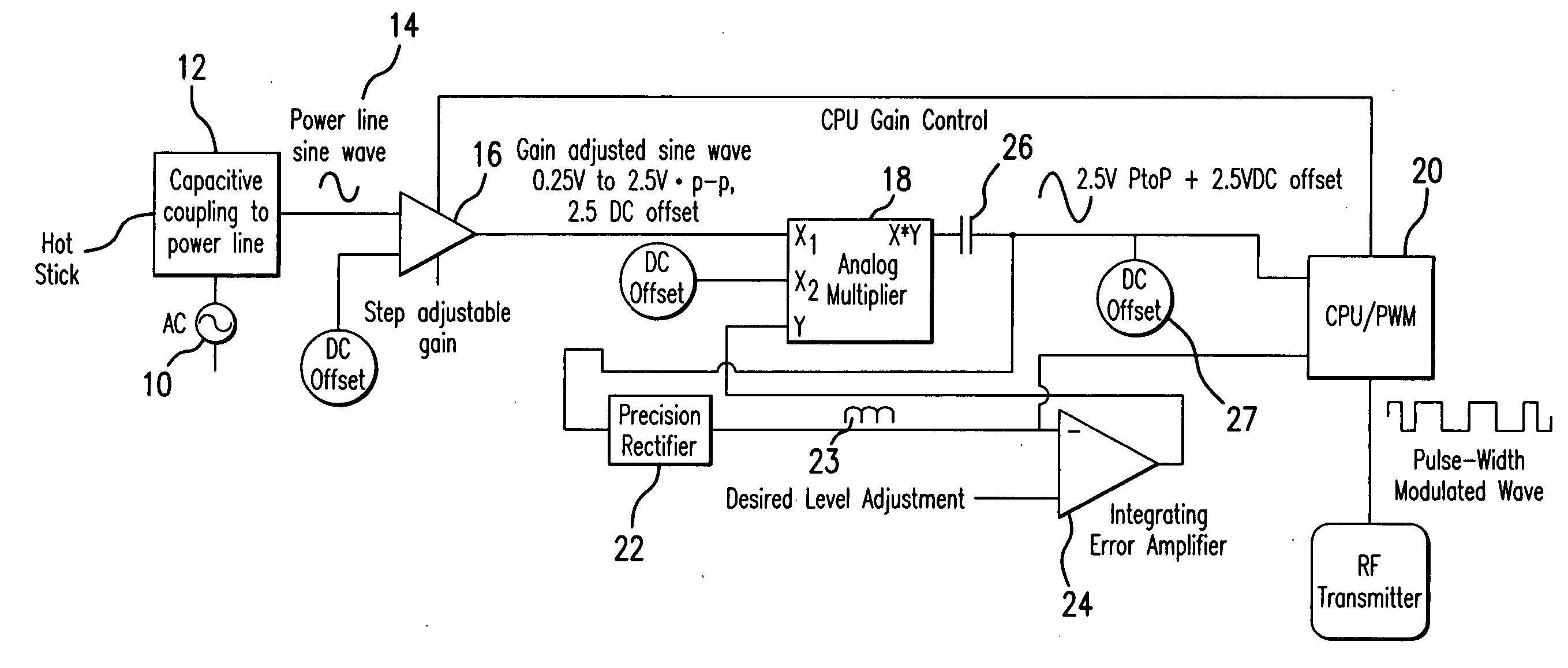
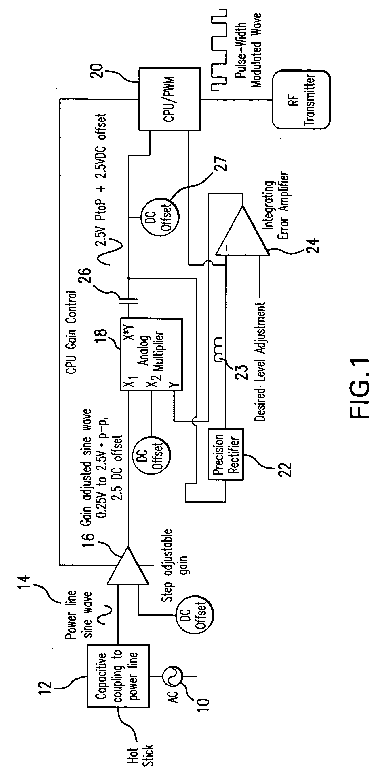
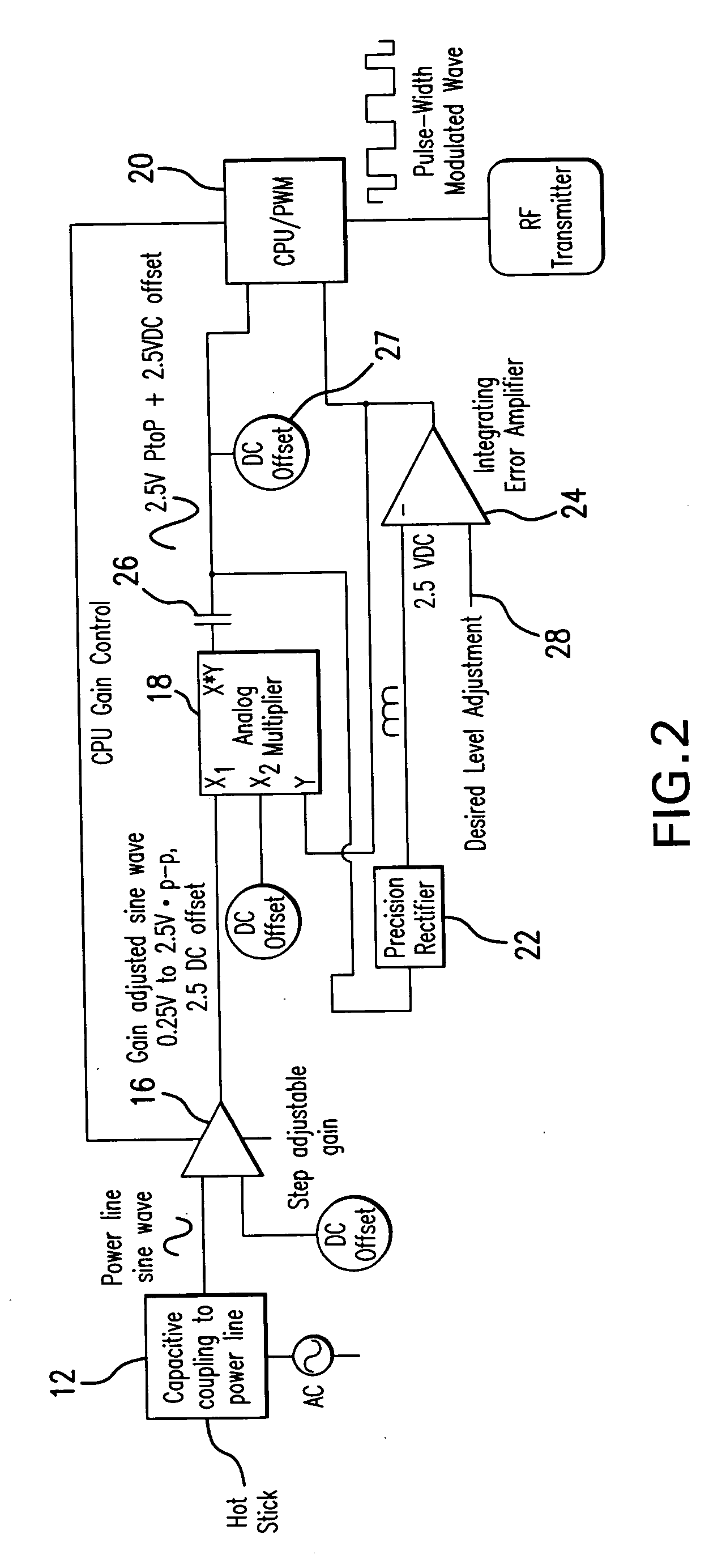
[0033] In FIG. 6 there is shown an overall block diagram of the primary units associated with an apparatus and method for remote phase identification of a remote field conductor with respect to a reference unit. A hot stick 1 is used to sense a voltage in a conductor. The hot stick transmits a sine wave to the field unit 2 where the sine wave contains all of the phase angle information. The transmission is a pulse width modulated FM RF modulated link. The inclusion of all phase angle information in the hot stick transmission takes advantage of the fast Fourier transform analysis which occurs in the field unit 2. A reference unit 3 senses voltage at a known location in a power system. Both the field unit 2 and the reference unit 3 receive time signals from a GPS transmitter which allows phase measurements to be made at the same known time. Also shown is a phase difference computer 4. This computer computes the difference between the phase angle at the field unit 2 and the phase angle...


PUM


Abstract

An apparatus for measuring phase angle difference between two conductors uses a hot stick, a field unit, and reference unit. Voltage is sensed at a conductor, and the voltage is passed through an automatic gain control which adjusts the voltage input to a voltage detector to a level which prevents saturation of the voltage detector. Non-saturation of the voltage detector enables detection of all of the data in a detected sine wave. Pulse width modulation and pulse width modulation RF transmission are used to provide for data transmission from a hot stick to a field unit.

Description

RELATED APPLICATIONS [0001] This application claims the priority of U.S. provisional application 60 / 719,209 filed on Sep. 22, 2005, which is incorporated herein by reference.BACKGROUND OF THE INVENTION [0002] 1. Field of the Invention [0003] This application is in the field of remote phase identification, which is often required in three phase power distribution systems. Remote phase identification is used in balancing loads in power distribution systems and in correctly repairing systems. Remote phase identification is preferable to line tracing to determine which phase is at a given point in a distribution system. More particularly, this invention provides a more accurate measure of phase at a field unit and at a reference unit than any available commercial devices. [0004] It is important to accurately identify each phase of a three-phase power distribution point to enable interconnection and reconnection of power lines when the path from the electrical generating station to the d...

Claims


Application Information

Patent Timeline
IPC IPC(8): H01R39/46
CPCG01R15/09G01R29/18G01R25/00G01R15/16
Inventor RHODES, GEORGE W.KESSLER, GARYMIGLIORI, ALBERT
Owner AVISTAR
Why Eureka
Try Eureka