Optical termination apparatus and optical transmission system

a technology of optical transmission system and optical termination apparatus, which is applied in the direction of optical elements, multiplex communication, instruments, etc., can solve the problems of insufficient or too high input power in the other onts, insufficient input power of data signal transceiver b>11/b> of the upstream optical wavelength, and insufficient input power of the data signal transceiver

Inactive Publication Date: 2007-03-22
HITACHI COMM TECH
View PDF3 Cites 29 Cited by
  • Summary
  • Abstract
  • Description
  • Claims
  • Application Information

AI Technical Summary

Benefits of technology

[0016] According to the invention, an optimal video signal is input to all the ONTs that receives the signal without fail although the video signal is deteriorated by SRS (Stimulated Raman Scattering) or SBS.
[0017] The above problem can be solved by an ONT including a multiplexer / demultiplexer connected to an optical fiber to multiplex / demultiplex the upstream data signal and downstream data signal and downstream video signal, a variable optical attenuator provided between the multiplexer / demultiplexer and a video optical receiver to adjust a level of the downstream video signal, and a controller for monitoring an output of the video optical receiver to adjust the variable optical attenuator.

Problems solved by technology

When the optical attenuator is inserted into the base station side, all the apparatuses on the end office side after the branching in the optical splitter need to have a certain amount of loss.
For example, when each of the ONTs does not have an equal loss, there is a possibility that although an appropriate optical power would be input in some of the ONTs, the input power could be insufficient or too high in the other ONTs because the dynamic range on the reception side of the video signal is very narrow, as described above.
However, the upstream optical wavelength also passes through the same optical attenuator 6, so that the input power to a data signal transceiver 11 of the upstream optical wavelength is likely to be insufficient.
Further, the adjustment is done manually, requiring the time and personnel costs for installation.
The loss value of the optical attenuator used for optical level adjustment is fixed by adjustment during installation, so that the video input power is likely to be out of the receivable range because of the change in the loss value of the fiber due to aged deterioration of the fiber or other factors.
There is another problem that in the case of transmitting plural wavelengths through a single fiber as the Triple-Play PON system, the wavelengths interfere with each other due to the nonlinear phenomenon of the optical fiber, causing signal deterioration.
Particularly, when the wavelengths defined by Document 1 are used, the power of the data wavelength moves to the video wavelength due to Raman effect and an interference occurs, thereby causing deterioration of the video signal because the downstream data wavelength is at 1490 nm band and the downstream video wavelength is at 1550 nm band.
Further, since the power of the wavelength used for the video signal is high ranging from +18 dBm to +20 dBm, SBS (Stimulated Brillouin Scattering) that is caused by reflection within the fiber occurs when a higher power is input to the fiber, causing deterioration of the video signal.

Method used


Image

  • Optical termination apparatus and optical transmission system
  • Optical termination apparatus and optical transmission system
  • Optical termination apparatus and optical transmission system

Examples


embodiment 1

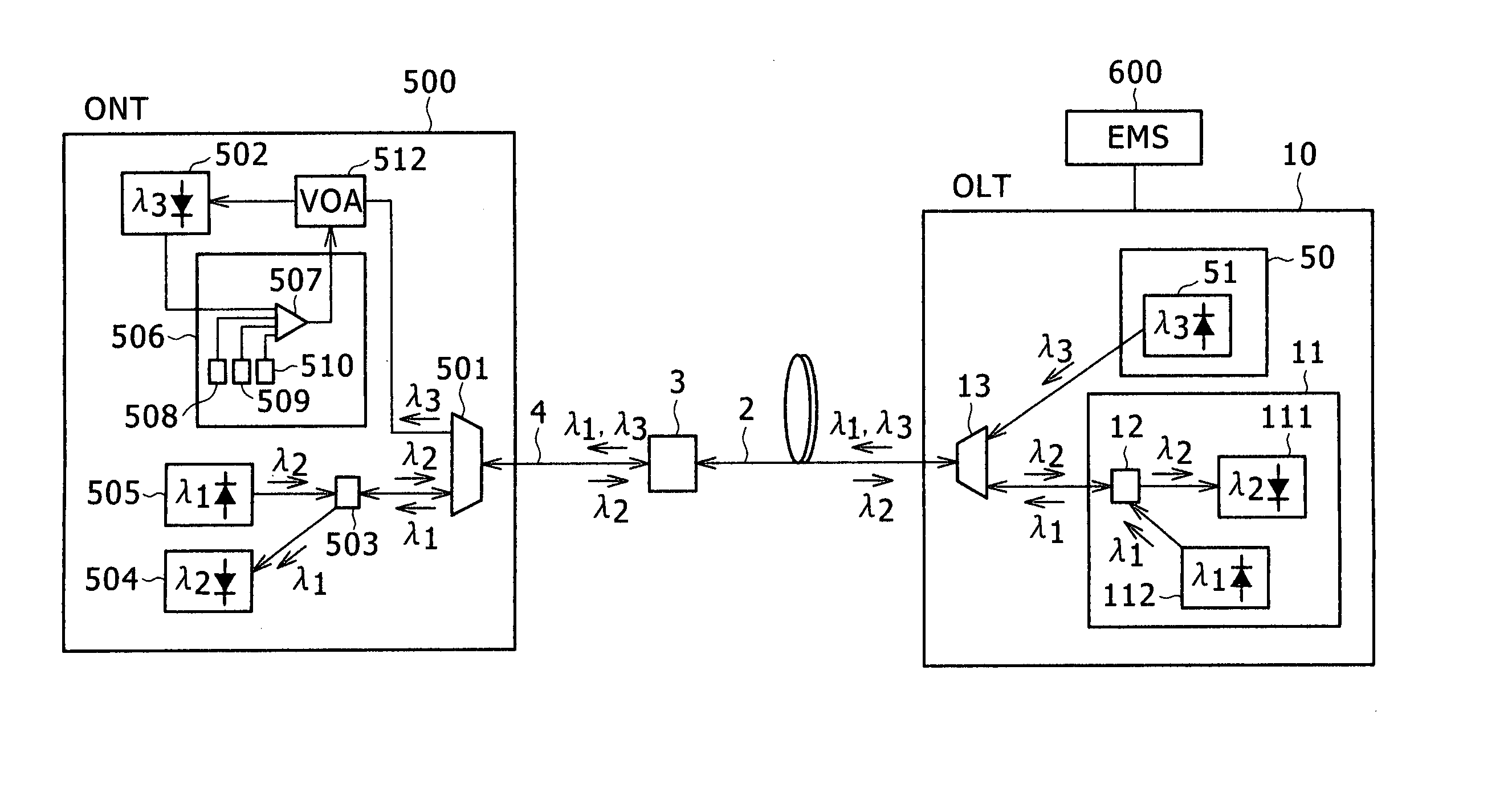
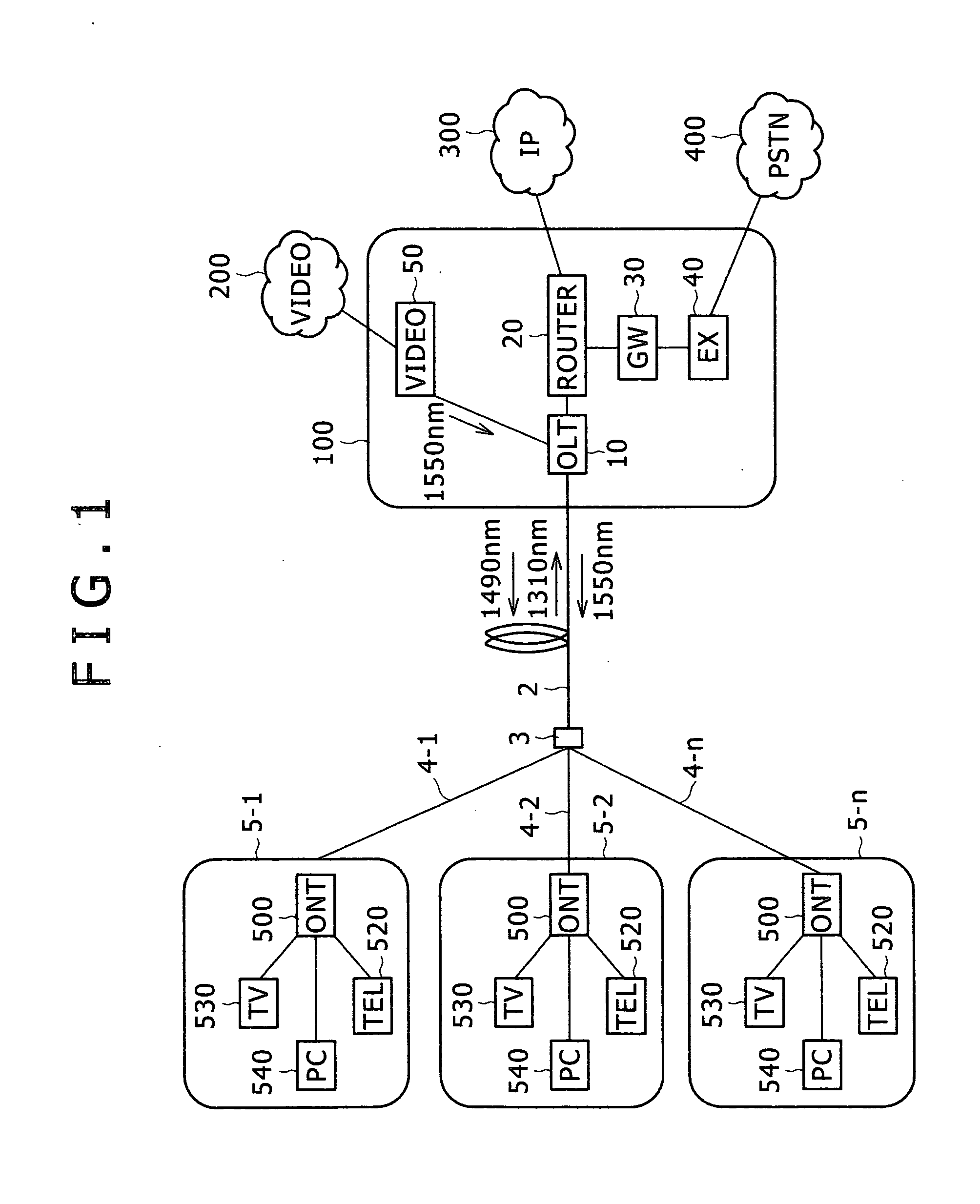
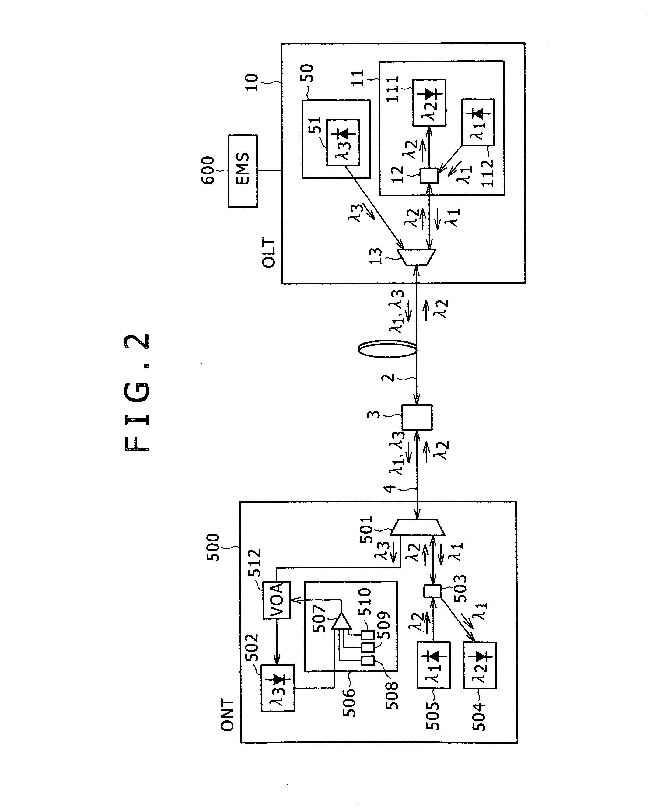
[0025] Embodiment 1 will be described with reference to FIGS. 2 and 3. Herein, FIG. 2 is a block diagram of a Triple-Play PON system. FIG. 3 is a control flowchart of an ONT. Incidentally, in FIG. 2 and the following figures, a video head end of FIG. 1 is referred to as a video signal transmitter. For illustrative convenience, the video signal transmitter is shown as being provided within the OLT 10. Also, only one subscriber's house is described in the figures.

[0026] In FIG. 2, the Triple-Play PON system includes an OLT 10 and an EMS (Element Management System) 600 that are placed in a central office, an ONT 500 placed in a subscriber's house, an optical splitter 3, a trunk line optical fiber 2, and a termination optical fiber 4. Herein, the EMS 600 is a monitoring device for the Triple-Play PON system. A data signal transceiver 11 of the OLT 10 is connected to a router 20 of FIG. 1. A video signal transmitter 50 of the OLT 10 is connected to a video network 200 of FIG. 1. Further,...

embodiment 2

[0036] Embodiment 2 will be described with reference to FIGS. 4 and 5. Herein, FIG. 4 is a block diagram of an ONT. FIG. 5 is a control flowchart of the ONT. Incidentally, the ONT 500 of FIG. 4 has substantially the same configuration as the ONT 500 of the Triple-Play PON system described using FIG. 2, and the description on the same or similar components will be omitted. Also in the control flow of FIG. 5, the description on the flow parts described using FIG. 3 will be simplified.

[0037] The ONT 500 shown in FIG. 4 is different from the ONT 500 described in FIG. 2 with respect to the following points. That is, that the part using the comparator 507 in FIG. 2 is replaced with an operation instruction circuit 513, where a portion of the reference voltage is changed. Further a CNR / CSO computation circuit 550 is newly provided. Herein, the CNR / CSO computation circuit 550 is a circuit for calculating the CNR (Carrier to Noise Ratio) value and the CSO (Composite Second Order beat) value,...


PUM


Abstract

A Triple-Player PON system is configured to have an optical line terminal (OLT) and an element management system (EMS), which are placed in a central office, an optical network terminal (ONT) placed in a subscriber's house, an optical splitter, a trunk line optical fiber, and a termination optical fiber. A variable optical attenuator is provided before a video optical receiver of the ONT, thereby to control the optical attenuation of the variable optical attenuator by a controller so that an input into the video optical receiver becomes an appropriate power.

Description

CLAIM OF PRIORITY [0001] The present application claims priority from Japanese patent application serial no. 2005-238318, filed on Aug. 19, 2005, the content of which is hereby incorporated by reference into this application. BACKGROUND OF THE INVENTION [0002] The present invention relates to an optical termination apparatus and optical transmission system, and more particularly to an optical network terminal and optical transmission system suitable for applying to a Triple-Play Passive Optical Network (Triple-Play PON) transmission system for transmitting voice, data and video through a single optical fiber. [0003] In North America, there is a growing need for a Triple-Play service that can provide high-speed data communication, voice communication and video delivery through a single optical fiber, in order for telecommunications companies such as RBOCs (Regional Bell Operating Companies) and CLECs (Competitive Local Exchange Carriers) to compete with cable TV companies. A Triple-P...

Claims


Application Information

Patent Timeline
Patent Type & Authority Applications(United States)
IPC IPC(8): G02B6/00H04B10/07H04B10/2507H04B10/2537H04B10/2543H04B10/27H04B10/272H04J14/00H04J14/02
CPCH04J14/0221H04J14/0226H04J14/0232H04J14/0247H04J14/0252H04J14/0282
Inventor MATSUOKA, TADASHISAKANO, SHINJI
Owner HITACHI COMM TECH
Why Eureka
Try Eureka