Electro-magnetic actuator for torque coupling with variable pressure-control spool valve

a torque coupling and variable pressure technology, applied in mechanical equipment, transportation and packaging, gearing, etc., can solve the problems of loss/draining of centrifugal fluid from the pump and the piston, failure of the differential system in terms of time delay and abrupt engagement, and loss of controllability of medium-to-high-speed handling maneuvers. achieve the effect of less amount and more accurate pressure control

Inactive Publication Date: 2007-03-29
DANA AUTOMOTIVE SYST GRP LLC
View PDF15 Cites 3 Cited by
  • Summary
  • Abstract
  • Description
  • Claims
  • Application Information

AI Technical Summary

Benefits of technology

[0064] One of the advantages of the present invention is its ability to precisely control the hydraulic fluid pressure generated by the hydraulic pump thanks to the spool valve which requires smaller valve actuation force when compared to compression type valves such as a ball valve or cone valve, thus less amount of electric power needed to control the torque-coupling assembly, and provides more accurate pressure control. As illustrated in FIG. 12, an output torque of the torque-coupling assembly of the present invention first increases in a Linear Control Regime as speed differential between the torque-coupling case and the output shaft increases, then the output torque increases albeit slower in a Pure Orifice Regime when the spool valve maintains its position. In other words, the spool valve is not affected by the rising hydraulic pressure generated by the pump, thus the torque-coupling assembly of the present invention has no “pressure defeat problem” of the torque-coupling assemblies of the prior art, illustrated in FIG. 1. It could also be noted by comparing the torque characteristics of FIGS. 1 and 12, that the torque increase of the torque-coupling assembly of the present invention is substantially more linear in the Linear Control Regime in comparison to the torque-coupling assembly of the prior art.
[0065] Another advantage of the torque-coupling assembly of the present invention is that the spool valve is formed inside the wall of the torque-coupling case so that the spool valve does not damage the compact packaging and the mechanical simplicity of the torque-coupling assembly.
[0066] Moreover, the inverted radial arrangement of the electro-magnetic coil assembly allows the fluid inlet and outlet holes and the exit opening be positioned at a smaller radial location, effectively eliminating the centrifugal fluid drain problem and allowing the torque coupling assembly to function properly in both the low-speed mobility and high-speed handling situations. Yet another advantage of this invention is that it provides above-mentioned benefits in a compact packaging of the pressure-control valve assembly.

Problems solved by technology

Prior-art pump type active limited slip differentials are acceptable for low-speed mobility situations (e.g. split-μ hill climb), but they lose its controllability for medium-to-high-speed handling maneuvers.
This failure of the pump-type coupling is caused by the fact that fluid inlet and outlet holes positioned at significantly high outer radius of the differential case, resulting in the centrifugal loss / draining of the fluid from the pump and the piston when the differential case is spinning.
As a result, when the differential case spins in response to the vehicle speed, the hydraulic fluid in the pump and the piston is centrifugally drained through the oil inlet and outlet holes, resulting in the failure of the differential system in terms of time delay and abrupt engagement of the clutch.
Therefore, the prior-art pump type active limited slip differentials fail to work for medium-to-high-speed handling maneuvers.
Another disadvantage of the prior-art active limited slip differentials is their use of the pressure-relief throttle valve in the form of a compression-type ball valve or cone valve that requires relatively high actuation force and suffers from a “pressure defeat problem”.
Thus, while known hydraulic couplings, including but not limited to those discussed above, have proven to be acceptable for some vehicular driveline applications and conditions, such devices are nevertheless unacceptable for some operational conditions and susceptible to improvements that may enhance their performance and cost.

Method used


Image

  • Electro-magnetic actuator for torque coupling with variable pressure-control spool valve
  • Electro-magnetic actuator for torque coupling with variable pressure-control spool valve
  • Electro-magnetic actuator for torque coupling with variable pressure-control spool valve

Examples


Embodiment Construction

[0026] The preferred embodiment of the present invention will now be described with the reference to accompanying drawings.

[0027] For purposes of the following description, certain terminology is used in the following description for convenience only and is not limiting. The words “right,”“left,”“lower,” and “upper” designate directions in the drawings to which reference is made. The words “outermost” and “innermost” refer to position in a vertical direction relative to a geometric center of the apparatus of the present invention and designated parts thereof. The terminology includes the words above specifically mentioned, derivatives thereof and words of similar import. Additionally, the word “a,” as used in the claims, means “at least one.”

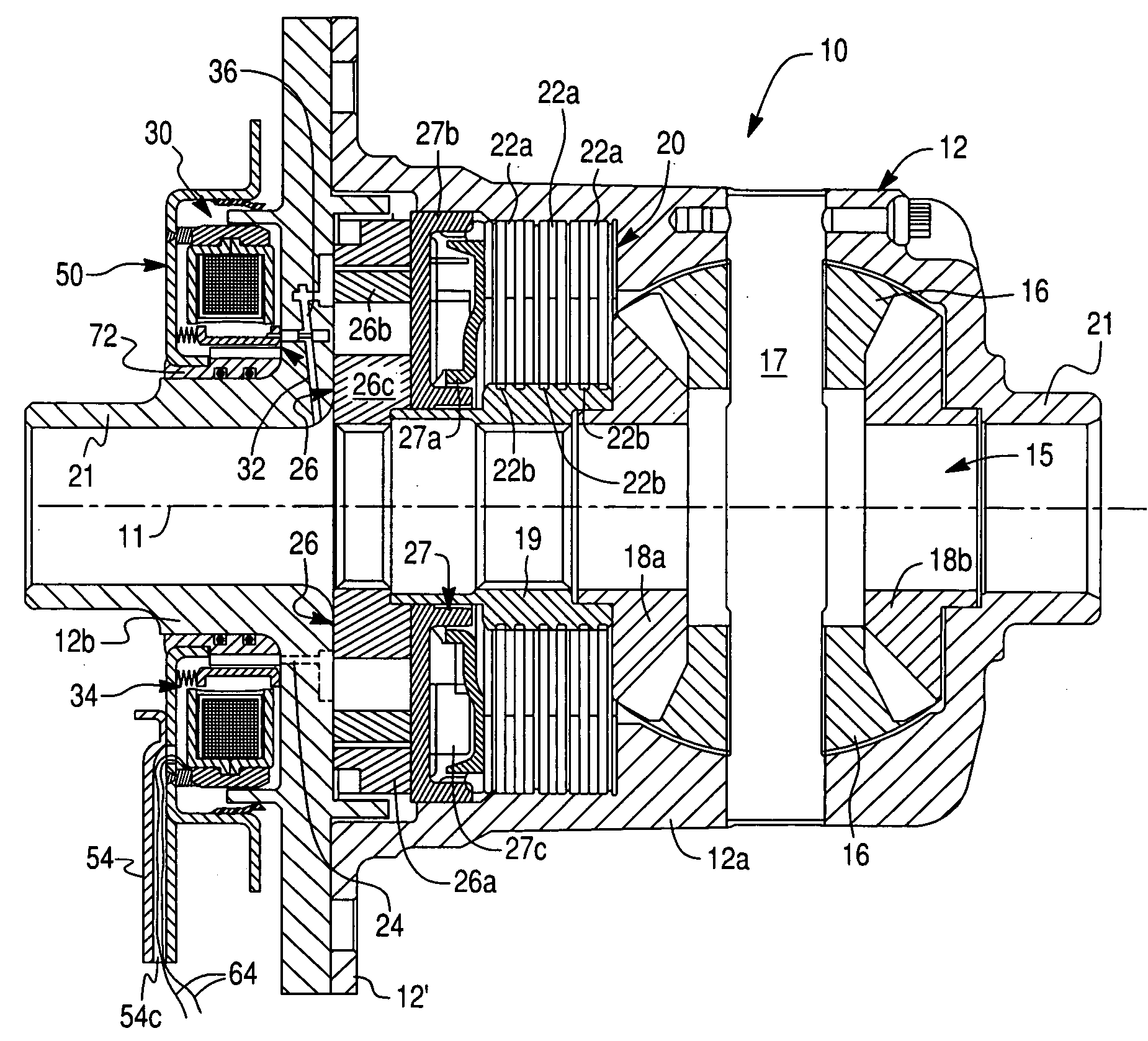
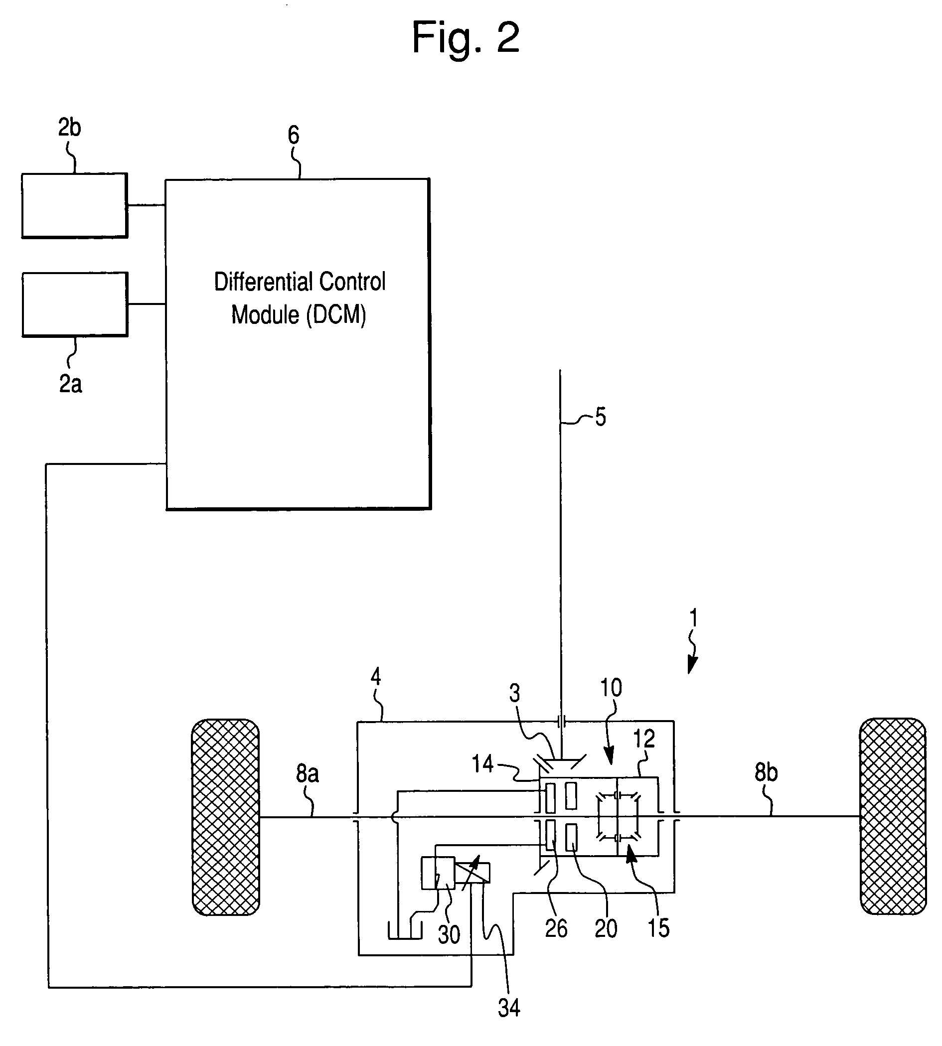
[0028] The present invention is directed to a hydraulically actuated torque coupling assembly including a hydraulic fluid pump, such as a hydraulically controlled limited slip differential (LSD) assembly indicated generally at 10 in FIGS. 2 and...


PUM


Abstract

A torque-coupling assembly comprises a rotatable torque-coupling case, a friction clutch assembly for selectively engaging the torque-coupling case and an output shaft, a hydraulic pump for generating a hydraulic fluid pressure, a fluid control passage through which a hydraulic fluid is discharged from the torque-coupling case, and a variable pressure-control valve assembly to selectively control the clutch assembly. The variable pressure-control valve assembly includes a spool valve disposed in the fluid control passage and an electromagnetic actuator. The electromagnetic actuator is provided for producing a variable axial electro-magnetic force acting to the spool valve so as to selectively adjust a position of the spool valve in the fluid control passage in order to selectively control a flow rate of the hydraulic fluid in the fluid control passage.

Description

BACKGROUND OF THE INVENTION [0001] 1. Field of the Invention [0002] The present invention relates to torque coupling assemblies in general, and more particularly to a torque coupling assembly including an electromagnetic actuator controlling a variable pressure-control valve. [0003] 2. Description of the Prior Art [0004] Hydraulic couplings are used in various vehicular drivetrain applications to limit slip and transfer drive torque between a pair of rotary members. In all-wheel drive applications, hydraulic couplings are used to automatically control the drive torque transferred from a driven member to a non-driven member in response to speed differentiation therebetween. In limited slip applications, couplings are used in association with a differential to automatically limit slip and bias the torque distribution between a pair of rotary members. [0005] Such hydraulic couplings conventionally use a friction clutch between the rotary members as a limited-slip device. The friction c...

Claims


Application Information

Patent Timeline
Patent Type & Authority Applications(United States)
IPC IPC(8): F16D25/0638F16H48/30
CPCF16D43/284F16H48/08F16H48/22F16H48/30F16H2200/2071F16H48/34F16H2048/204F16H2048/346F16H2048/382F16H48/32
Inventor PARK, JUNGHO
Owner DANA AUTOMOTIVE SYST GRP LLC
Why Eureka
Try Eureka