Disc drive apparatus

a disc drive and drive shaft technology, applied in the direction of instruments, disposition/mounting of heads, maintaining the alignment of the head carrier, etc., can solve the problems of not being able to increase the gain unlimitedly, the effect of increasing the gain and keeping the gain constan

Inactive Publication Date: 2007-03-29
KONINKLIJKE PHILIPS ELECTRONICS NV
View PDF4 Cites 0 Cited by
  • Summary
  • Abstract
  • Description
  • Claims
  • Application Information

AI Technical Summary

Benefits of technology

[0018] According to an important aspect of the present invention, the gain increase in the case of a shock not only depends on the strength of the shock but also depends on the characteristic frequency of the shock. If the shock has a relatively low or relatively high associated frequency, the gain i...

Problems solved by technology

Position errors may, in practice, be caused by different types of disturbances.
A problem in this respect is that adequately handling disturbances of the first category requires a different control characteristic than...

Method used


Image

  • Disc drive apparatus
  • Disc drive apparatus
  • Disc drive apparatus

Examples


Embodiment Construction

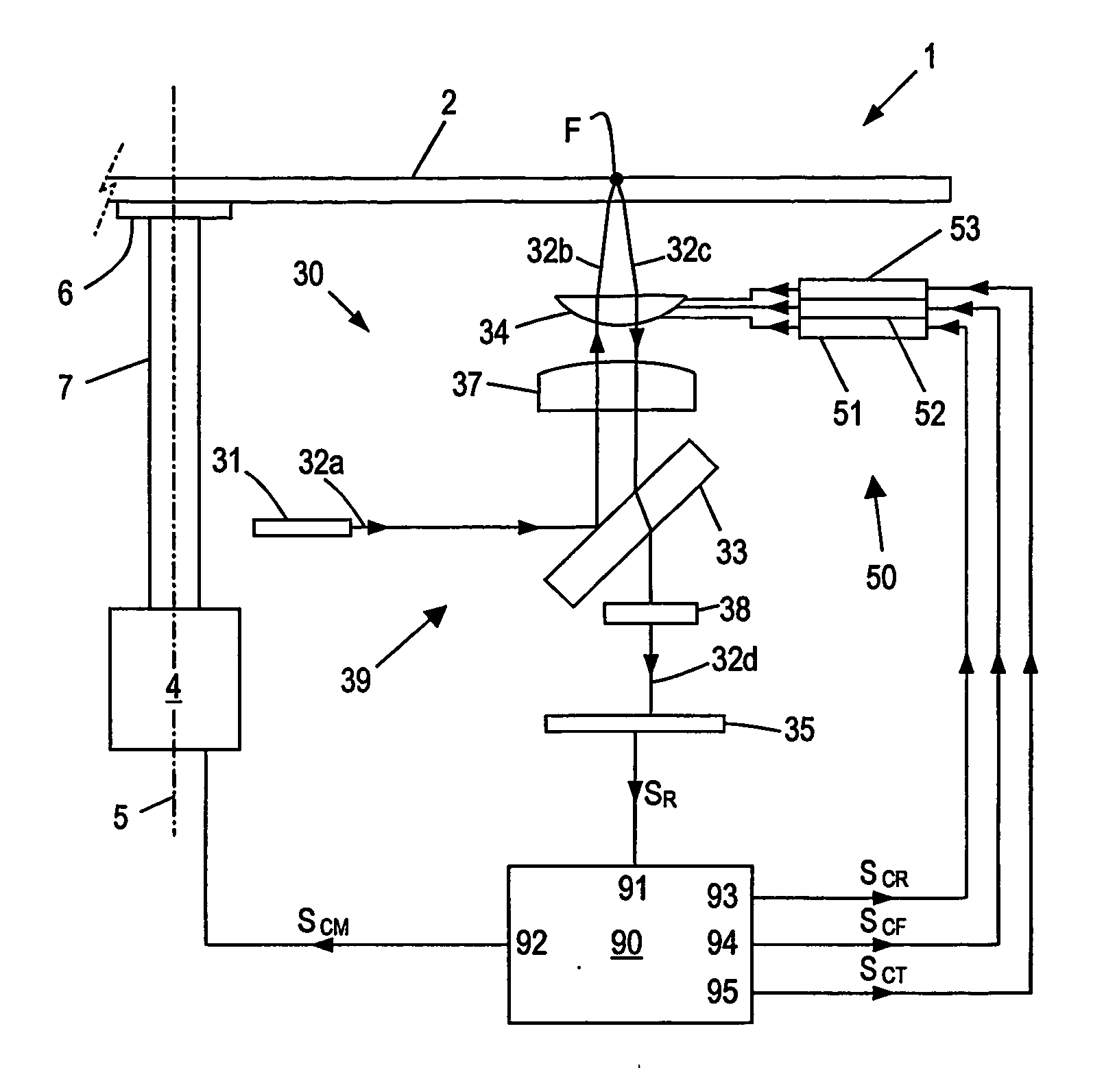
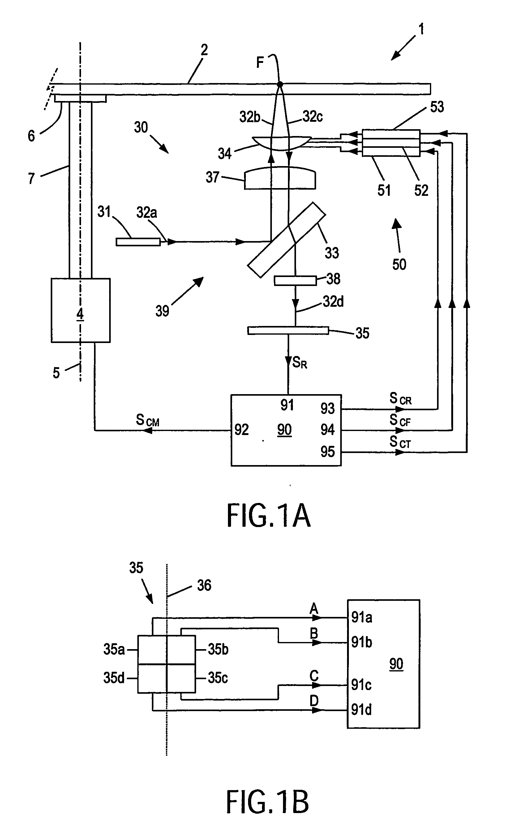
[0029]FIG. 1A schematically illustrates an optical disc drive apparatus 1, suitable for storing information on or reading information from an optical disc 2, typically a DVD or a CD. For rotating the disc 2, the disc drive apparatus 1 comprises a motor 4 fixed to a frame (not shown for sake of simplicity), defining a rotation axis 5.

[0030] The disc drive apparatus 1 further comprises an optical system 30 for scanning tracks (not shown) of the disc 2 by an optical beam. More specifically, in the exemplary arrangement illustrated in FIG. 1A, the optical system 30 comprises a light beam generating means 31, typically a laser such as a laser diode, arranged to generate a light beam 32. In the following, different sections of the light beam 32, following an optical path 39, will be indicated by a character a, b, c, etc added to the reference numeral 32.

[0031] The light beam 32 passes a beam splitter 33, a collimator lens 37 and an objective lens 34 to reach (beam 32b) the disc 2. The o...


PUM


Abstract

A method is described for controlling an optical disc drive apparatus (1) of a type comprising: scanning means (30) for scanning a record track of an optical disc (2), said scanning means (30) comprising at least one read/write element (34) to be positioned with respect to the disc (2), and at least one optical detector (35) for generating a read signal (SR); actuator means (50) for controlling the positioning of said at least one read/write element (34); a control circuit (290) for receiving said read signal (SR) and generating at least one actuator control signal (SCR) on the basis of at least one signal component of said read signal (SR), the control circuit (290) having at least one variable gain (γ); said control circuit (290), said actuator means (50), said read/write element (34), and said optical detector (35) defining a control loop (200) having a critical frequency (ωCP); the method comprises the steps of: selectively setting the gain (γ), for signal components having a frequency in a predefined range corresponding to said critical frequency (ωCP), to a value lower than a value for signal components having a frequency outside said range.

Description

FIELD OF THE INVENTION [0001] The present invention relates in general to a disc drive apparatus for writing / reading information into / from a storage disc. Although the gist of the invention also applies to magnetic discs, the present invention specifically applies to optical discs, for which reason the invention will hereinafter be described for optical discs, while the corresponding disc drive apparatus will also be indicated as “optical disc drive”. BACKGROUND OF THE INVENTION [0002] As is commonly known, an optical storage disc comprises at least one track, either in the form of a continuous spiral or in the form of multiple concentric circles, of storage space where information may be stored in the form of a data pattern. Optical discs may be read-only type, where information is recorded during manufacturing, which information can only be read by a user. The optical storage disc may also be a writeable type, where information may be stored by a user. For writing information in t...

Claims


Application Information

Patent Timeline
IPC IPC(8): G11B7/00G11B5/55G11B5/596G11B7/09G11B21/10
CPCG11B5/5582G11B5/596G11B21/106G11B7/0946G11B7/0948G11B7/0941G11B7/00G11B7/09G11B7/095
Inventor HEERTJES, MARCEL FRANCOISSPERLING, FRANK BERNHARD
Owner KONINKLIJKE PHILIPS ELECTRONICS NV
Why Eureka
Try Eureka