Ultrasonic transducer having a digital interface

Active Publication Date: 2007-03-29
FUJIFILM SONOSITE
View PDF33 Cites 28 Cited by
  • Summary
  • Abstract
  • Description
  • Claims
  • Application Information

AI Technical Summary

Benefits of technology

[0007] The present invention is directed to systems and methods in which signal processing functionality is partitioned such that a portion of the ultrasound signal processing is contained within the transducer assembly of an ultrasound system, thereby reducing the need for a multiplicity of high performance conductors, or other relatively high bandwidth, high fidelity bandwidth running between the transducer and the main b

Problems solved by technology

The cable is also typically large and heavy because it carries the transmit and receive signals for a number of individual elements of the transducers, located in the transducer head.
The length, usually in excess of six feet, coupled with the weight of the cable places significant stress and strain on a sonographer.
The cable also adds significant cost and complexity to the system.
Another problem with exi

Method used


Image

  • Ultrasonic transducer having a digital interface
  • Ultrasonic transducer having a digital interface
  • Ultrasonic transducer having a digital interface

Examples


Embodiment Construction

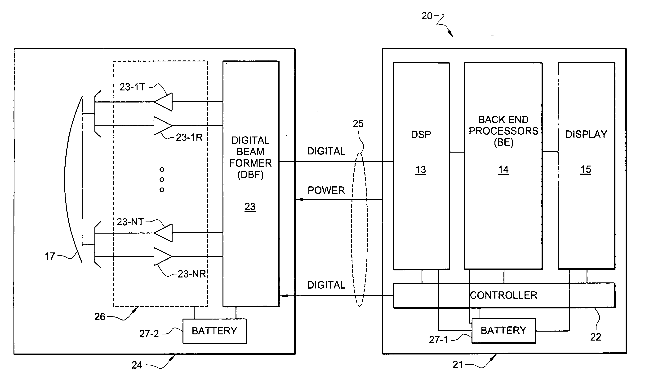
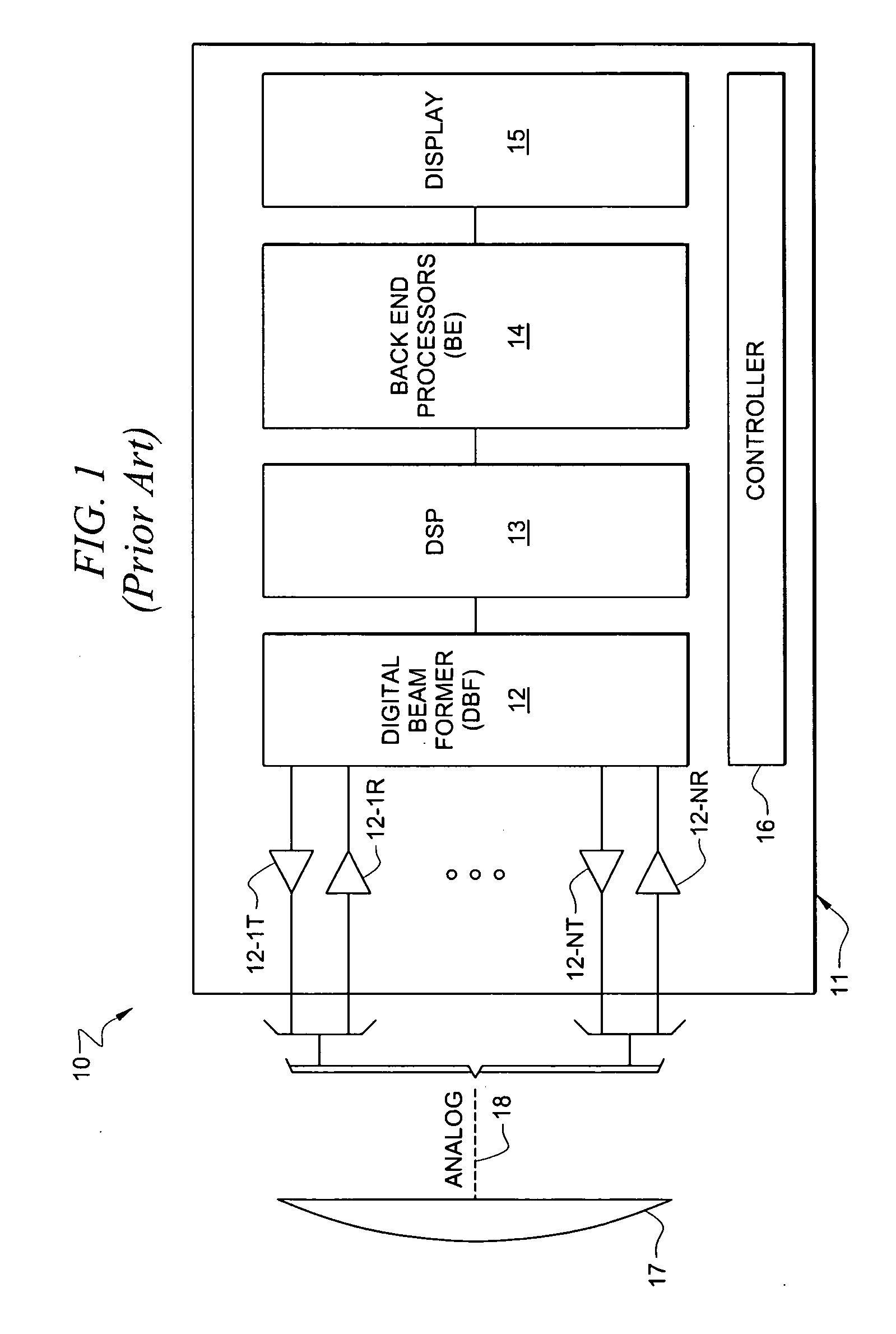
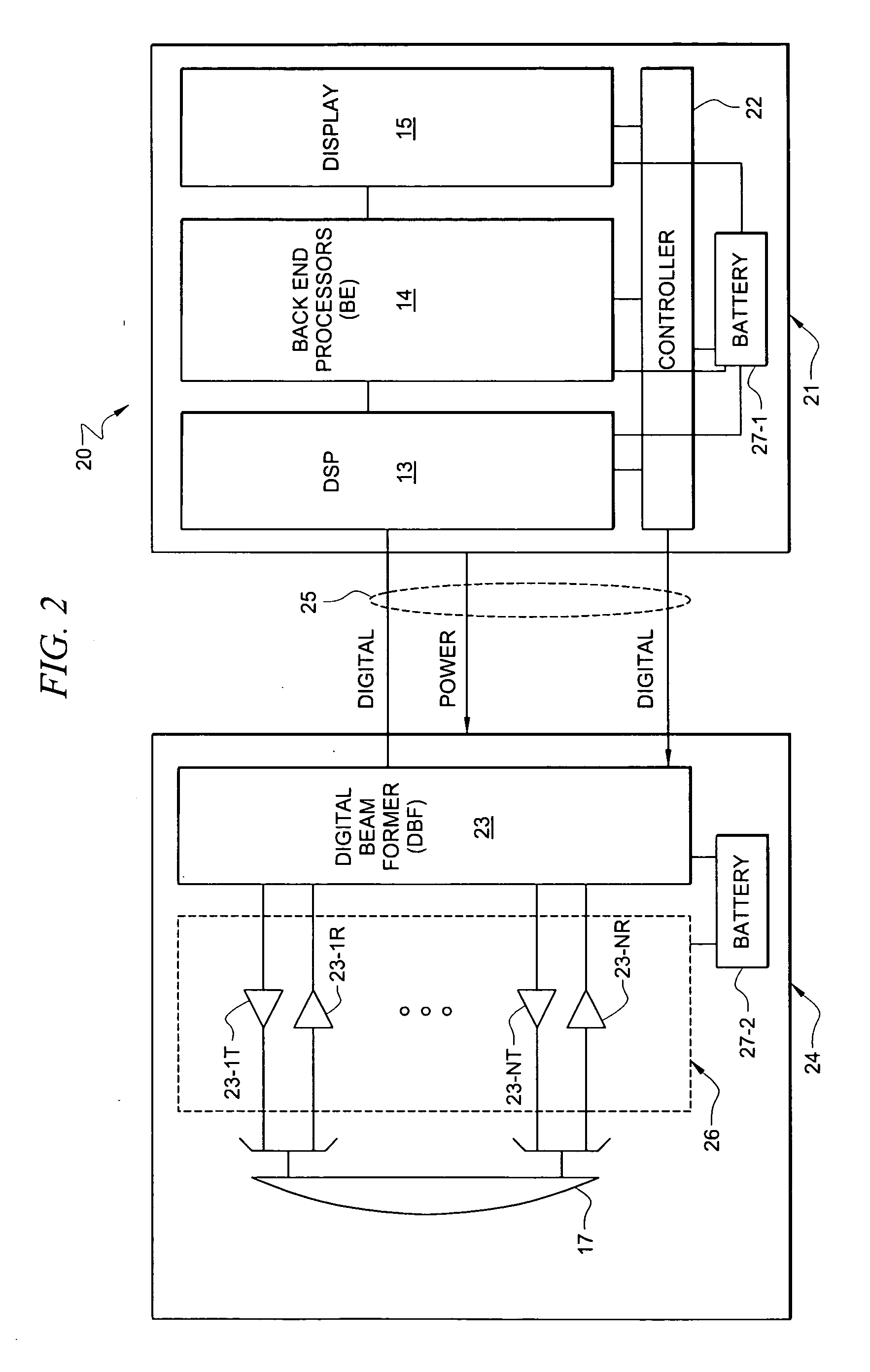
[0016]FIG. 1 shows a typical prior art architecture of an ultrasound system as system 10 having transducer array 17, which is coupled via analog cable 18 to individual receiving and transmit channels 12-IT, 12-IR to 12-NT, 12-NR to digital beam former 12. Typically, the Tx and Rx signals are time multiplexed. DSP 13 is comprised of circuits utilized for echo and flow signal processing and includes analytic signal detection and compression, multi-rate filtering, and moving target detection capabilities. Digital signal processor (DSP) 13 provides signals to and receives signals from beam former 12. Back end processing 14 then provides signals to drive display 15 all under control of controller 16. Display 15 provides for display of data including image data. This display could be disposed in main processing unit housing 11, or could be separate from both the main processing unit and from the transducer assembly. The operation of processing elements as set forth above can be as discuss...


PUM


Abstract

Systems and methods which partition ultrasound signal processing between an ultrasound system main processing unit and transducer assembly are shown. A particular division of signal processing functionality disposed in the main processing unit and the transducer assembly may be selected to provide a desired weight balance, a desired level of processing for data communication between the main processing unit and the transducer assembly, etcetera. Battery capacity may additionally or alternatively be partitioned between the main processing unit and the transducer assembly.

Description

CROSS-REFERENCE TO RELATED APPLICATIONS AND PATENTS [0001] The present application is a continuation-in-part of co-pending, commonly assigned, patent application Ser. No. 10 / 925,144 entitled “Ultrasonic Transducer Having A Thin Wire Interface,” filed Aug. 24, 2004, the disclosure of which are hereby incorporated herein by reference. The present application is related to co-pending, and commonly-assigned U.S. patent application Ser. No. 10 / 924,390, entitled “Ultra System Power Management,” filed on Aug. 24, 2004; U.S. patent application Ser. No. 10 / 847,643, filed on May 17, 2004, entitled “Processing Of Medical Signals;” U.S. patent application Ser. No. 10 / 821,123, filed on Apr. 8, 2004, entitled “Systems And Methods For Providing ASICS For Use In Multiple Applications;” U.S. patent application Ser. No. 10 / 821,198, filed on Apr. 8, 2004, entitled “System And Method For Enhancing Gray Scale Output On A Color Display;” the disclosures of which are all hereby incorporated.TECHNICAL FIEL...

Claims


Application Information

Patent Timeline
IPC IPC(8): H04R25/00
CPCA61B8/00A61B8/4455A61B8/4472G01S15/8909G01S7/003G01S7/5208G01S7/52082A61B8/565A61B8/4444
Inventor LITTLE, BLAKEDUNBAR, LEE
Owner FUJIFILM SONOSITE
Why Eureka
Try Eureka