
Automatic gain control

a gain control and automatic technology, applied in the field of data communication systems and methods, can solve the problems of special problems of automatic gain control, burst mode data transmission poses challenges to maintaining signal gain control, and inhibit effective data communication, so as to improve receiver sensitivity and responsiveness, and reasonable cost

Inactive Publication Date: 2007-03-29
MRV COMMUNICATIONS
View PDF5 Cites 30 Cited by
  • Summary
  • Abstract
  • Description
  • Claims
  • Application Information

AI Technical Summary

Benefits of technology

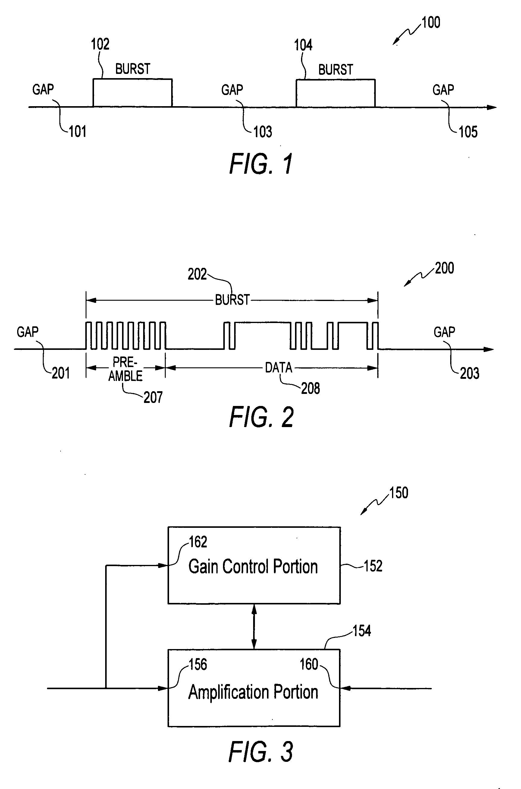
[0024] In various embodiments, the devices and systems disclosed are adapted to provide optimized signal reception characteristics during a quiescent signal interval and during an active signal interval. For example, the embodiments disclosed include embodiments adapted to operate in a burst mode data system so as to respond effectively to both quiescent intervals and bursts of data. One embodiment of the invention includes a receiving device that responds rapidly to a signal transition that follows a quiescent interval so as to avoid the loss of leading data of a data burst, and thereafter responds less rapidly so as to avoid premature state transitions in the event of quiescent intervals within the data burst. One embodiment includes an automatic gain control device with an adaptable time constant. An exemplary automatic gain control device is adaptable by switching or otherwise changing a time constant thereof so as to be optimized for a type of or portion of a data pattern being received.
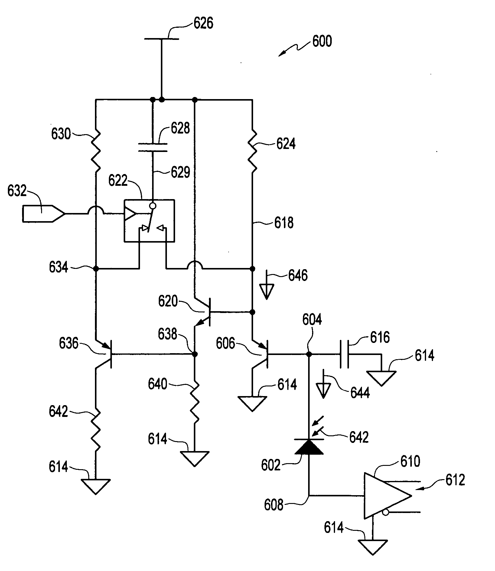
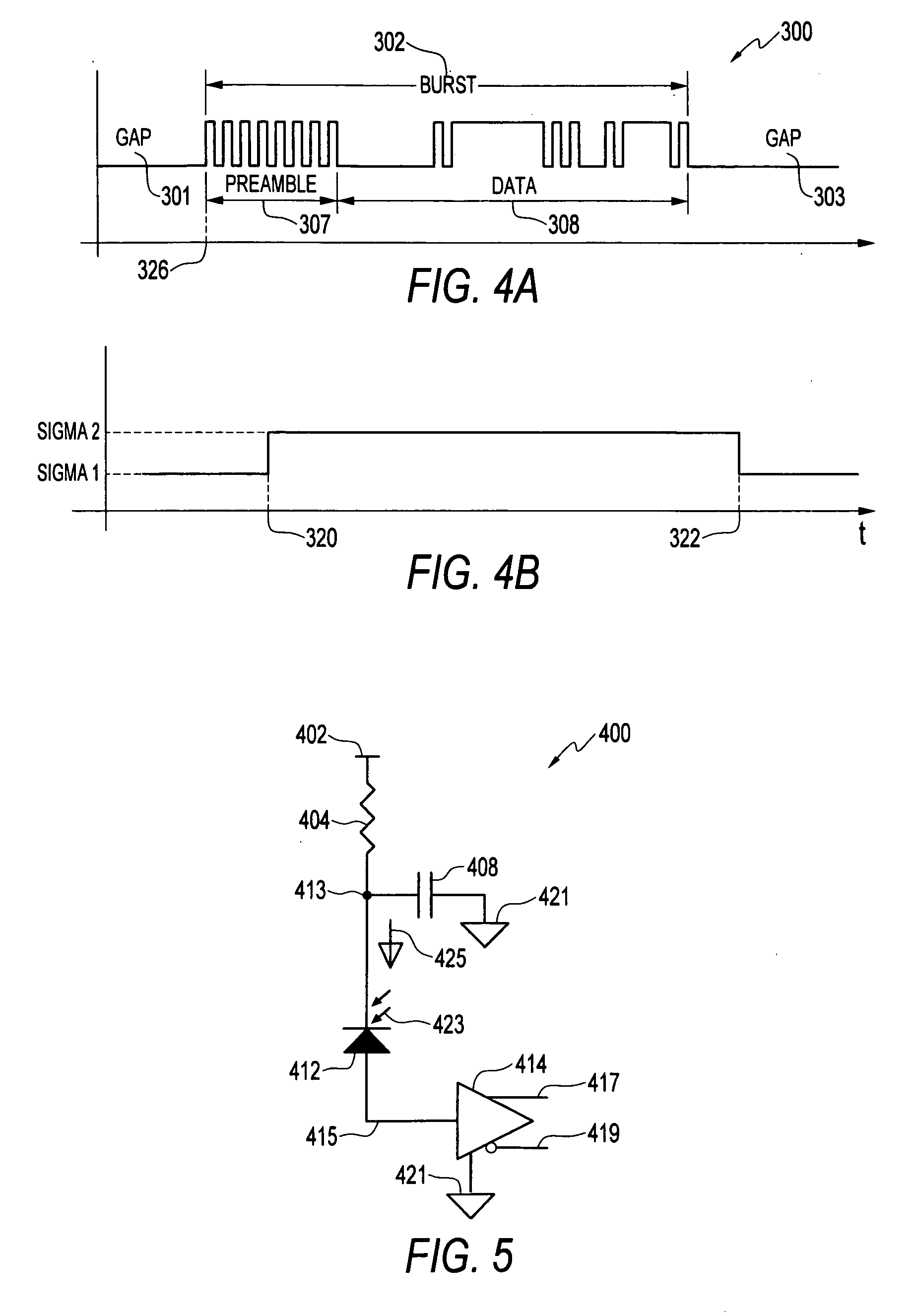
[0025] In an optical communications system, for example, an automatic gain control device is coupled to an avalanche photodiode and a transimpedance amplifier. One such embodiment includes an APD, a TIA, and an AGC device in which the time constant of an RC combination is controllable by switchingly coupling a capacitor in and out of parallel connection with a resistor. The AGC device is coupled to the avalanche photodiode and the transimpedance amplifier in such a way that the reverse bias voltage applied to the APD may be adjusted according to a DC average of an incoming data pattern to avoid saturation of the TIA. A switch device in the AGC device may be used to increase or decrease the time constant of the RC combination determining the DC averaging time period, thereby tailoring the response of the AGC device to characteristics of the incoming datastream. A resulting receiver exhibits improved responsiveness and sensitivity to data patterns including bursts of one or more packets interspersed with gaps.
[0027] When employed in the context of optical communications, for example, one embodiment of the present invention significantly improves receiver sensitivity and responsiveness by adapting to varying data patterns including those with data bursts interspersed with gaps. Methods and devices embodying these advantages may be provided in a form suitable for use with conventional data transmission networks and at a reasonable cost.

Problems solved by technology

In addition to relocking and resynchronization, burst mode data transmission poses challenges to maintaining signal gain control.
In data communications generally, variations in the strength of a received signal can inhibit effective data communication.
When high amplitude signals are received, however, such a sensitive receiver can become saturated so that variations in an input signal received at the amplifier are not represented in the output signal produced by the amplifier.
Burst mode data poses special problems for automatic gain control.
A long time constant (slow response) AGC has its own problems, however.
Such an AGC will not be very responsive to actual variation in signal strength over the course of a data burst.
Under such circumstances, however, larger signal amplitude, and DC bias, can readily cause saturation of the TIA.
Once the TIA has saturated, the output of the TIA does not respond effectively to changes at its input.
In such systems, slow AGC response can reduce overall sensitivity of the receiver for a data pattern including data bursts and gaps.

Method used


Image

  • Automatic gain control
  • Automatic gain control
  • Automatic gain control

Examples


Embodiment Construction

[0041] The following description is provided to enable a person of ordinary skill in the art to make and use the disclosed inventions and sets forth the best modes presently contemplated by the inventors for carrying out their inventions. In the following description, for purposes of explanation, numerous specific details are set forth in order to provide a thorough understanding of the described inventions. It will be apparent to one skilled in the art, however, that the inventions may be practiced without these specific details. In other instances, structures and devices are shown in block diagram (or otherwise simplified) form for clarity of presentation.

[0042] In the following discussion, the singular term “signal” and plural term “signals” are used interchangeably and are to be understood as including analog or digital information, at a single frequency or a plurality of frequencies, and may or may not include coding, modulation, sideband information, or other features of sign...


PUM


Abstract

A method and apparatus is presented for providing improved responsiveness of a receiver device. One embodiment includes a receiver device including an avalanche photodiode (APD), a transimpedance amplifier (TIA), and an automatic gain control (AGC) device configured to adjust the reverse bias voltage applied to the APD according to an approximate DC average of the incoming optical signal. A switch in the AGC device may be used to increase or decrease the time constant of an RC combination determining the DC averaging time period, thereby tailoring the response of the AGC device to characteristics of the incoming data pattern. The resulting receiver exhibits improved responsiveness and sensitivity by adapting to varying data patterns including those with data bursts interspersed with gaps.

Description

CROSS REFERENCE TO RELATED APPLICATION [0001] This application claims the benefit under 35 U.S.C. § 119(e) of U.S. Provisional Application No. 60 / 701,864, entitled “INSTANTANEOUS AUTOMATIC GAIN CONTROL FOR AVALANCHE PHOTODIODES WITH SWITCHABLE TIME CONSTANT,” filed Jul. 25, 2005, the contents of which are hereby incorporated by reference in their entirety.FIELD OF THE INVENTION [0002] The present invention relates to data communication systems and methods and, more particularly, to intermittent data communication systems and methods. BACKGROUND OF THE INVENTION [0003] Data communication systems and methods are used in the transmission of information for an increasing variety of purposes, including the control of equipment. As such, improving the performance of data communication systems has become an important focus of attention. For example, optical communication systems are continually undergoing improvement in many areas related to transmission performance such as capacity, bandw...

Claims


Application Information

Patent Timeline
IPC IPC(8): H04B10/06
CPCH04B10/691H03G3/3084
Inventor MARGALIT, NEARREGEV, ZVI
Owner MRV COMMUNICATIONS
Learn More