Thruster with electro-thermal thrust augmentation

a technology of electro-thermal thruster and thruster, which is applied in the field of thruster augmentation of liquid propellant rocket thrusters, can solve the problems of limiting the useful operational life of an ev, ev cannot be controlled or maneuvered, and severe weight and volume limitations of an ev, so as to improve the specific impulse (isp) of the ev's thruster, simplify the thruster design, and improve the resistance to hydrazine products

Inactive Publication Date: 2007-04-05
THE STATE OF ISRAEL MINIST OF AGRI & RURAL DEV AGRI RES ORG ARO VOLCANI CENT
View PDF9 Cites 7 Cited by
  • Summary
  • Abstract
  • Description
  • Claims
  • Application Information

AI Technical Summary

Benefits of technology

[0037] It is yet one more object of the present invention to provide a thruster (100) wherein the at least one resistor includes a plurality of resistors electrically coupled in appropriate parallel and serial electrical connection to provide low electric resistance and a large heat exchange surface, thus with the required electric resistance and with an enlarged heat exchange surface.

Problems solved by technology

Evidently, there are severe weight and volume limitations for an EV.
The amount of propellant carried on board is usually the decisive factor limiting the useful operational life of an EV.
Furthermore, the propellant supply of the EV cannot usually be replenished after launch, and hence, once exhausted, the EV can no longer be controlled or maneuvered.
However, indirect heating complicates the thruster's structure, adds to its weight, increases response time, and boosts costs.
Moreover, indirect heating calls for a larger temperature difference between the heater and the heated gas than would be otherwise necessary, because of the additional thermal resistance penalty inflicted by the partition.
The higher heater temperature also leads to a shorter heater operational life, to higher heat losses, and therefore to higher power requirement for a given performance.
In addition, regarding thermal isolation and heat removal of excess heat from the EV, the problems involved become more elaborate, requiring sophisticated and expensive solutions.

Method used


Image

  • Thruster with electro-thermal thrust augmentation
  • Thruster with electro-thermal thrust augmentation
  • Thruster with electro-thermal thrust augmentation

Examples


second embodiment

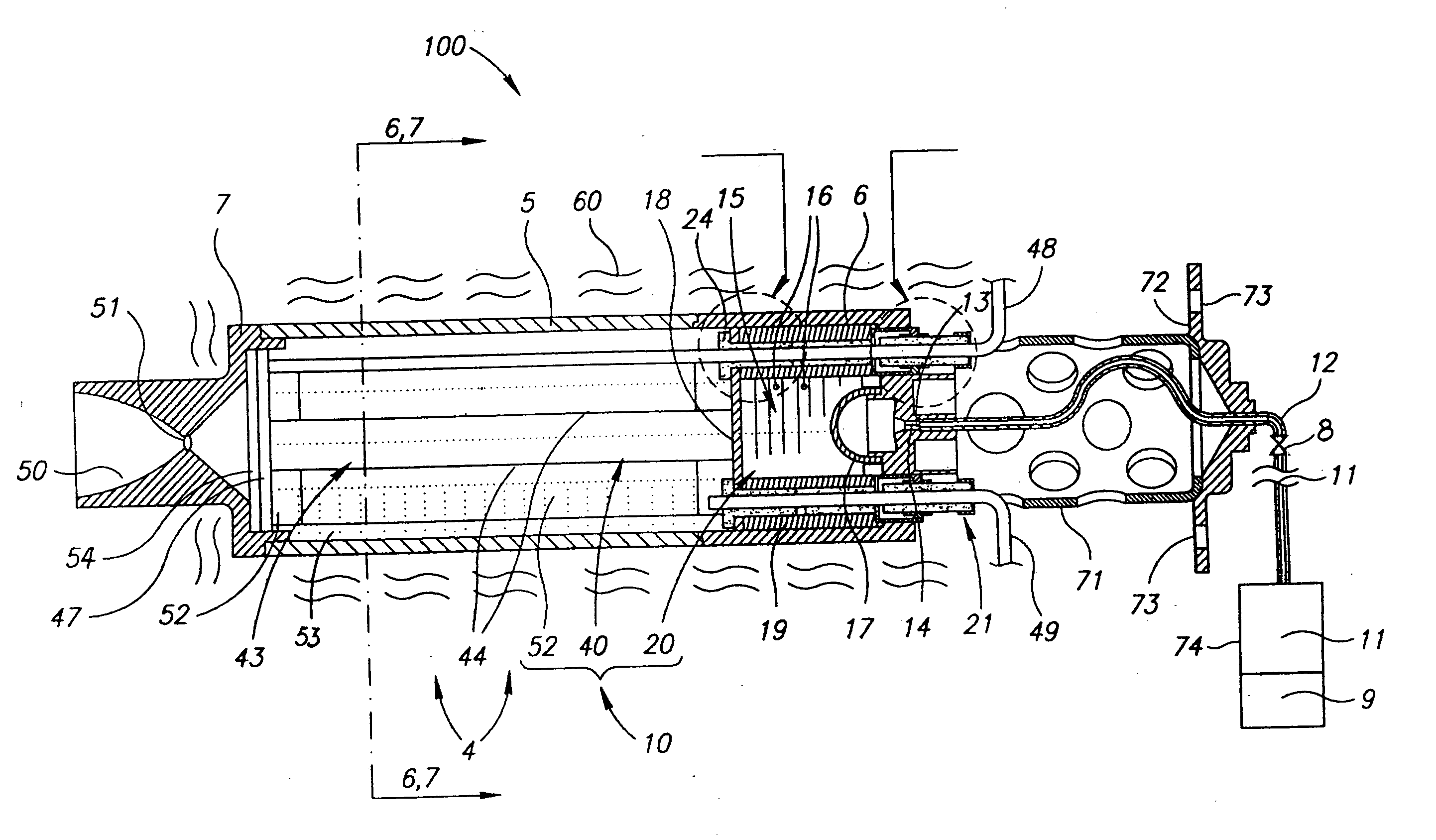
[0060] In FIGS. 2B and 2C there is shown the heating section 40. A first and a second U-shaped electric resistor, respectively resistor 81 and resistor 82, have each two straight longitudinal parallel arm portions and a base portion. Both U-shaped resistors, 81 and 82, are disposed with their arm portions in parallel, and with their respective base perpendicularly adjacent to each other, downstream near the side of the discharge plug 7, which is indicated in FIG. 1. The arm portion of each U-shaped resistor, 81 and 82, is covered by a coaxial concentric external tube 83. It is shown in FIG. 2C that longitudinal fins 87 accommodated inside each external tube 83 firmly support a respective arm portion of each U-shaped resistor, 81 and 82.

[0061] If desired, although not shown in the Figs., the first and second U-shaped resistors 81 and 82 may be of identical shape and dimensions, but disposed with their base portion side-by-side in parallel, instead of in cruciform disposition, as show...

fourth embodiment

[0071] In each one of the first, third, and fourth embodiment of the heating module 43, voids in the heating section 40 are filled with the catalyst 15, such as the pellets mixture 46, as indicated in FIGS. 6 and 7. The enhanced heat transfer properties of the additive serve to improve the heat exchange process resulting in higher gas temperature.

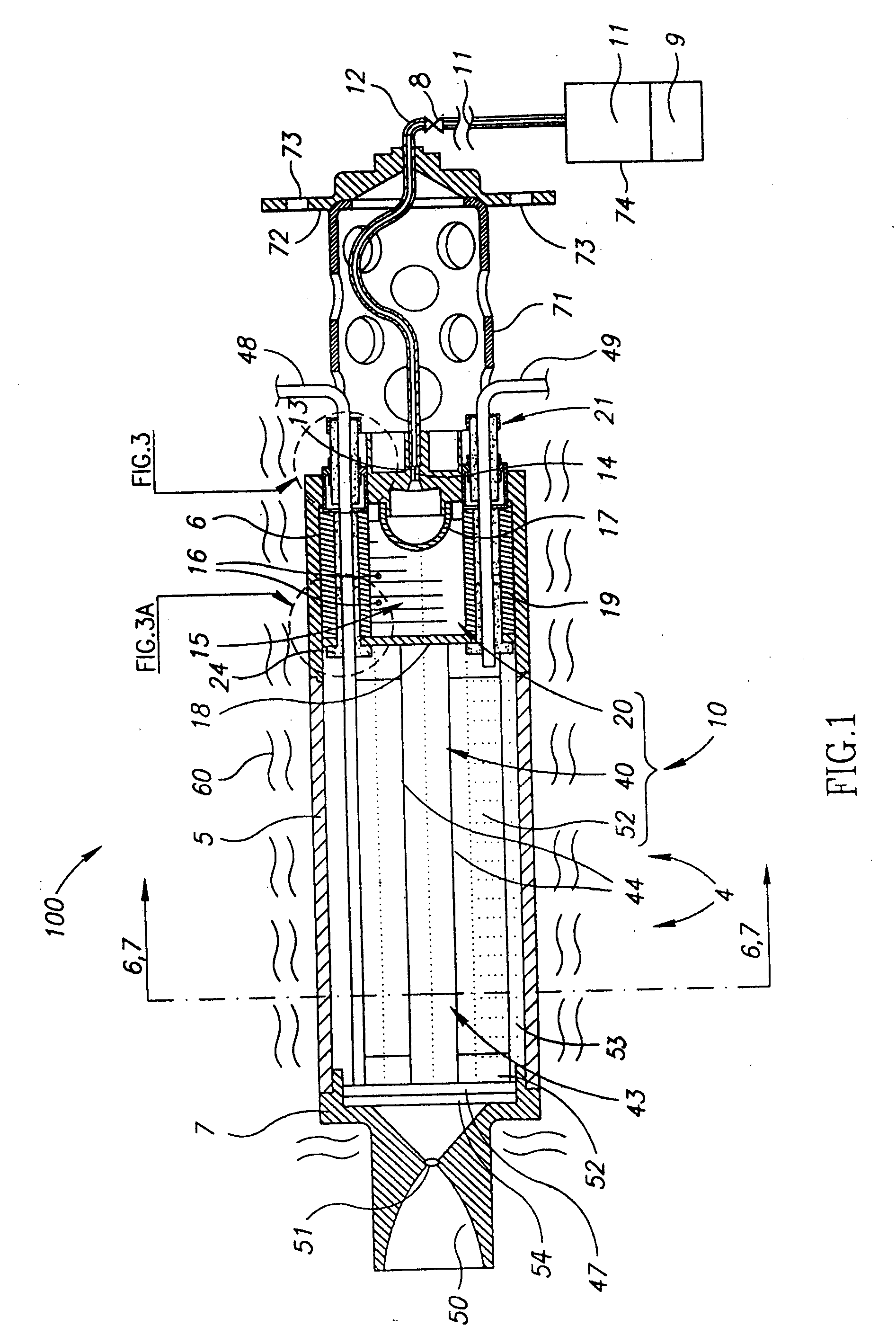
[0072] Ceramic rods 350, shown in FIG. 7, which duct the flow toward the center and along the axis of the heating section 40, are attached to sleeve 5 by means of a welded toggle, not shown in the Figs. In the first embodiments depicted in FIGS. 2A and 7, two electrically insulating holders 47, shown only in FIG. 2A, retain together resistors 44 and 244. Each insulating holder 47 has at least one aperture 45 accommodated to permit the flow of the hot gasses therethrough. In all of the shown configurations, screen 54 is attached to holder 47, at least adjacent discharge plug 7, to prevent spilling of the pellets mixture 46 through aperture 4...


PUM

PropertyMeasurementUnit
Timeaaaaaaaaaa
Pressureaaaaaaaaaa
Poweraaaaaaaaaa

Abstract

A thruster for exo-atmospheric vehicles with electro-thermal thrust augmentation and having internally embedded heating elements for direct contact heating of gaseous products released by a propellant, particularly hydrazine, so as to increase the Specific Impulse (Isp) of the thruster. The electrical heating elements are resistant to hydrazine products. The thruster is configured as a closed sealed chamber divided into a decomposition section upstream and a heating section downstream. At least one heating element is disposed in the heating section, directly in a mixture catalyst forming a porous bed, or within a concentric ceramic tube operative as a heat exchanger, to heat the gaseous products by direct contact. The heater indirectly heats the catalyst in the decomposition section and directly heats the heating section. The thruster is operable both in space and at sea-level gravity and barometric pressure.

Description

[0001] The present application claims the benefit of Israel Patent Application No. 159248 filed on 08 Dec. 2003 and is a Continuation of PCT / IL2004 / 001108 filed on 06 Dec. 2004 FIELD OF THE INVENTION [0002] The present invention relates to thrust augmentation of liquid propellant rocket thrusters in general, wherein the thrust augmentation is achieved by electro-thermally heating the gaseous propellant products, and in particular to hydrazine rocket thrusters used for maneuvering and for station-keeping of satellites and spacecraft. BACKGROUND OF THE INVENTION [0003] The orbits and the orientations of satellites and of other exo-atmospheric vehicles, referred to as “EV” hereinbelow, require correction to compensate for the effect of drag and drift, to correct trajectory such as for insertion into orbit and for change of orbit, and for fulfilling further operational requirements. Some of these corrections are carried out by small rocket thrusters, named “thrusters” hereinbelow, using...

Claims


Application Information

Patent Timeline
IPC IPC(8): F03H1/00B64GF03H
CPCB64G1/406F02K9/42F05D2300/21F02K9/68F05D2260/20F02K9/60B64G1/415
Inventor OREN, AHARON
Owner THE STATE OF ISRAEL MINIST OF AGRI & RURAL DEV AGRI RES ORG ARO VOLCANI CENT
Why Eureka
Try Eureka