Method for manufacturing electrode layer for fuel cell

Inactive Publication Date: 2007-04-05
HONDA MOTOR CO LTD
View PDF4 Cites 10 Cited by
  • Summary
  • Abstract
  • Description
  • Claims
  • Application Information

AI Technical Summary

Benefits of technology

[0018] Preferably, the step for evaporating the solvent on the front surface comprises heating the electrode material layer to a temperature that allows the solvent con

Problems solved by technology

This fact is an obstruction to increas

Method used


Image

  • Method for manufacturing electrode layer for fuel cell
  • Method for manufacturing electrode layer for fuel cell
  • Method for manufacturing electrode layer for fuel cell

Examples


Example

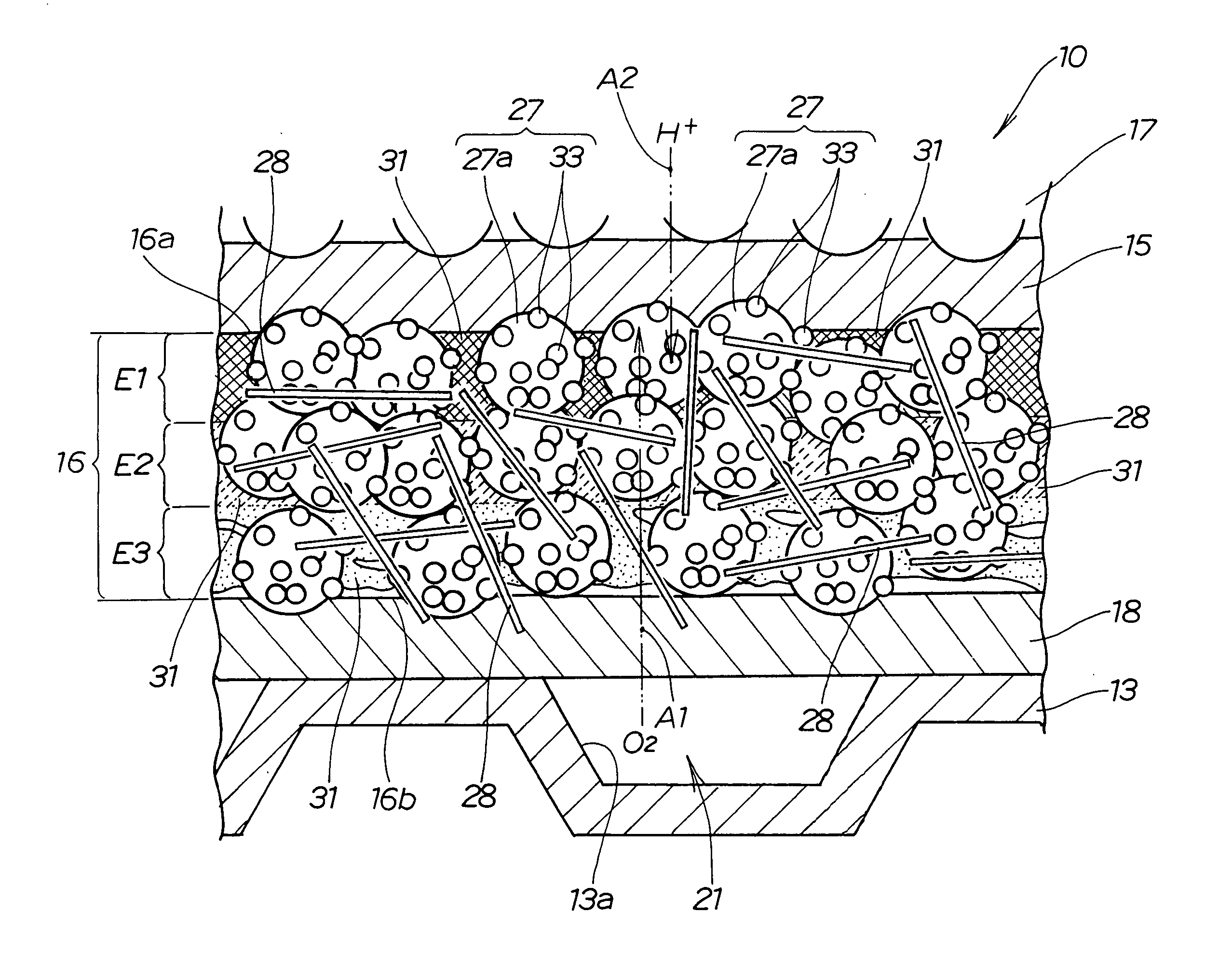
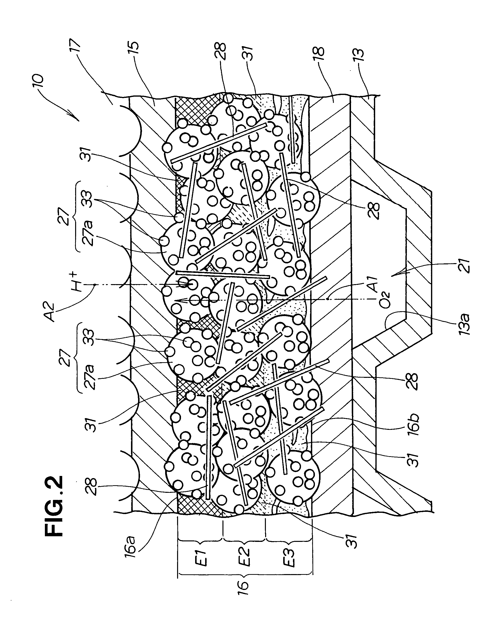
[0103] The cathode of the comparative example is a sample obtained by applying electrode paste 41A (see FIG. 3) to a base material 42 (see FIG. 3) and solidifying the paste by drying while the ion-exchange resin / carbon ratio is set to 1.4 across the entire electrode paste 41A. In other words, the cathode of the comparative example was manufactured without using the fourth step described above. The first and second ion-exchange resin / carbon ratios in the solidified cathode of the comparative example were determined by the measurement method described above.

[0104] The results are shown in FIG. 7B. According to these results, the first ion-exchange resin / carbon ratio 1PE / C in the cathode of the comparative example was 1.4 as indicated by the ♦ mark, and the second ion-exchange resin / carbon ratio 2PE / C in the cathode was 1.4 as indicated by the ▪ mark. In other words, in the cathode of the comparative example, the 1PE / C and the 2PE / C have the same value, making it apparent that the wei...


PUM


Abstract

A method for manufacturing an electrode layer for a fuel cell includes applying a paste-form electrode material, having a solvent that includes an ion-exchange resin, to a sheet-form base, and evaporating the solvent on a front surface of a layer of the electrode material so that the concentration of the ion-exchange resin in the electrode material layer formed on the base increases from a front surface toward a reverse surface, opposed to the base, of the electrode material layer.

Description

FIELD OF THE INVENTION [0001] The present invention relates to a method for manufacturing an electrode layer for a fuel cell, wherein a paste-form electrode material is applied to a sheet-shaped base material, and the coated electrode material is solidified to form an electrode layer. BACKGROUND OF THE INVENTION [0002] A common fuel cell is configured in the manner shown in FIG. 12 hereof showing a main part of a common fuel cell. [0003] A common fuel cell 100 comprises an ion-exchange membrane 101, a cathode 102 laminated to one surface of the ion-exchange membrane 101, an anode 103 laminated to the other side of the ion-exchange membrane 101, a cathode diffusion layer 104 laminated to the cathode 102, and an anode diffusion layer 105 laminated to the anode 103. The cathode diffusion layer 104 has an external oxygen gas channel (not shown). The anode diffusion layer 105 has an external hydrogen gas channel (not shown). [0004] Oxygen gas fed from the oxygen gas channel flows into th...

Claims


Application Information

Patent Timeline
IPC IPC(8): H01M4/88
CPCH01M4/8642H01M4/8803H01M4/881H01M4/8828H01M4/8882H01M2004/8689H01M2008/1095Y02E60/50
Inventor TAMAI, TOMOKOSHIBUTANI, TOMOHIDEKOBAYASHI, YOUHEI
Owner HONDA MOTOR CO LTD
Why Eureka
Try Eureka