
Vehicle dynamics control system adapted to the load condition of a vehicle

Inactive Publication Date: 2007-04-05
ROBERT BOSCH GMBH
View PDF25 Cites 26 Cited by
  • Summary
  • Abstract
  • Description
  • Claims
  • Application Information

AI Technical Summary

Benefits of technology

[0009] It is an object of the present invention to create a method for rollover stabilization of vehicles, as well as a corresponding driving dynamics control system with which the loading state of a vehicle, and consequently its rollover tendency, may be estimated in a simple way and may be taken into consideration within the scope of a rollover stabilization algorithm.
[0015] According to a second specific example embodiment of the present invention, the position of the vehicle's center of gravity, and especially the height of the center of gravity may be estimated from an examination of the contact patch forces of the wheels at an inside and an outside wheel during cornering. At a high mass center of gravity, the contact patch force at the outer wheel is comparatively higher than for a low mass center of gravity (at equal mass of the payload) at the same transverse acceleration. Because of the increased tendency of the vehicle to roll over, the outer wheels are more greatly unloaded at high mass center of gravity. From the ratio of the contact patch forces FN1 / FNr of an inner and an outer wheel, one may thus qualitatively estimate the height of the vehicle's center of gravity.
[0017] According to a third specific example embodiment of the present invention, the estimating methods described in specific embodiments 1 and 2 may be combined, in order to achieve a qualitative improvement and a greater availability of the estimated height of the center of gravity.

Problems solved by technology

Vehicles having a high center of gravity, such as minivans, SUV's (sport utility vehicles), or vans, are prone to rolling over about the longitudinal axis, in particular when cornering at a transverse acceleration that is too high.
A substantial cause for rollover of a vehicle about the longitudinal axis is, generally, too high a transverse acceleration.
In addition, constructive features, such as the suspension, may change depending on age, and consequently may affect the rollover tendency of the vehicle.
This means that, at normal or low loading, the rollover stabilization interventions may take place too early or too energetically.

Method used


Image

  • Vehicle dynamics control system adapted to the load condition of a vehicle
  • Vehicle dynamics control system adapted to the load condition of a vehicle
  • Vehicle dynamics control system adapted to the load condition of a vehicle

Examples


Embodiment Construction

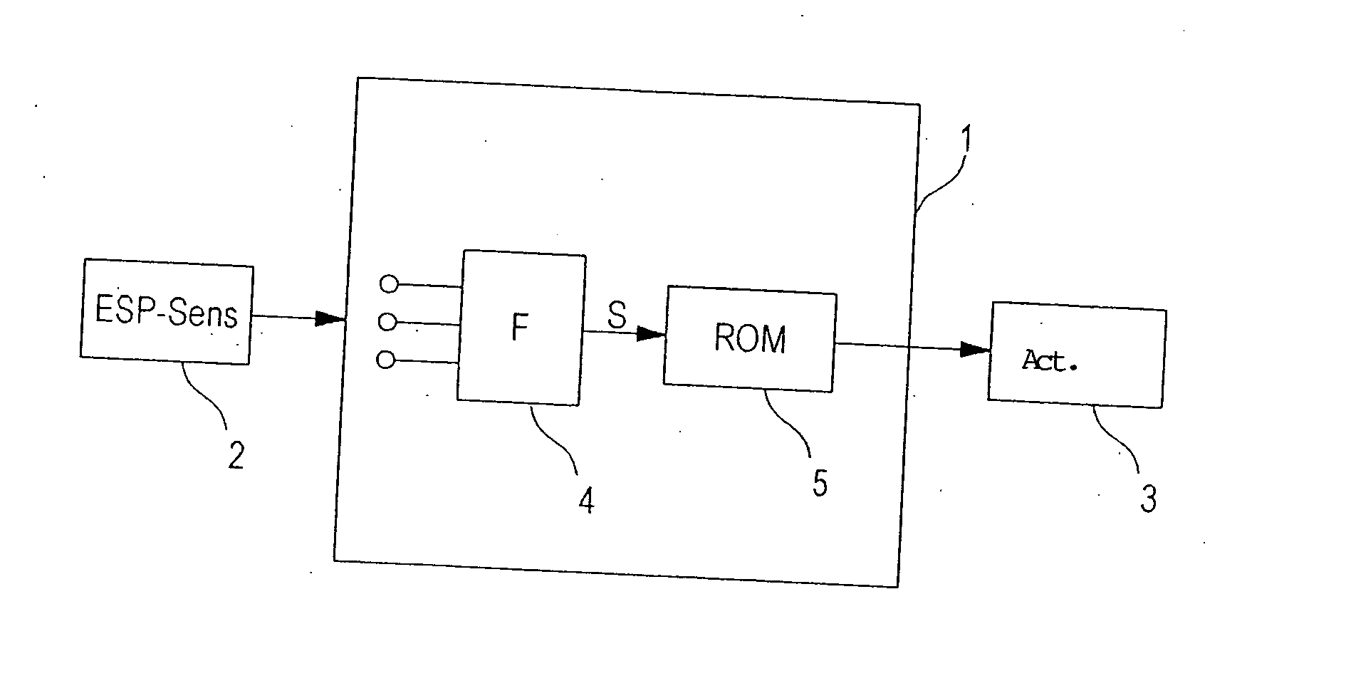
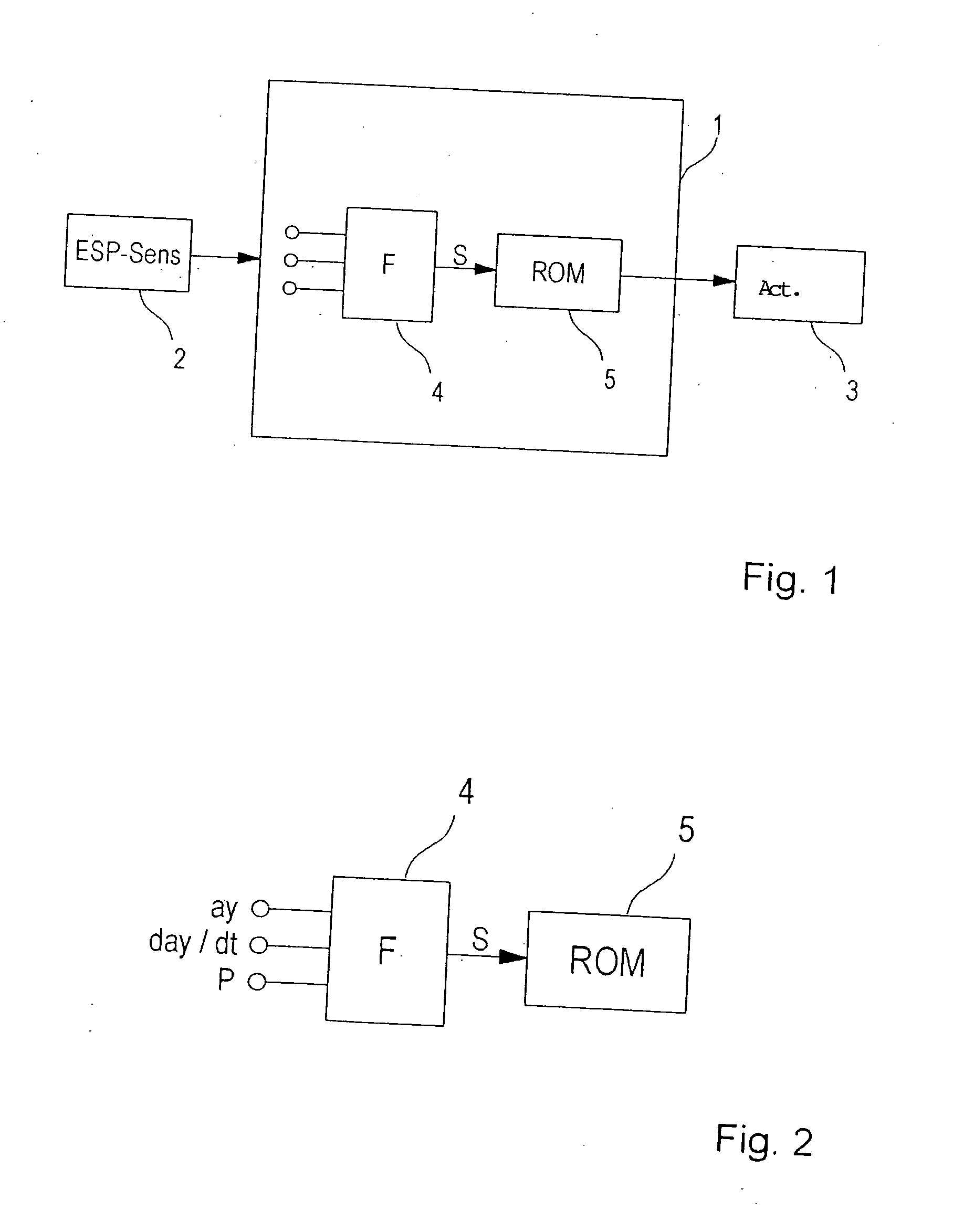
[0027] Reference is made to the introductory part of the specification regarding the clarification of FIGS. 1 and 2.

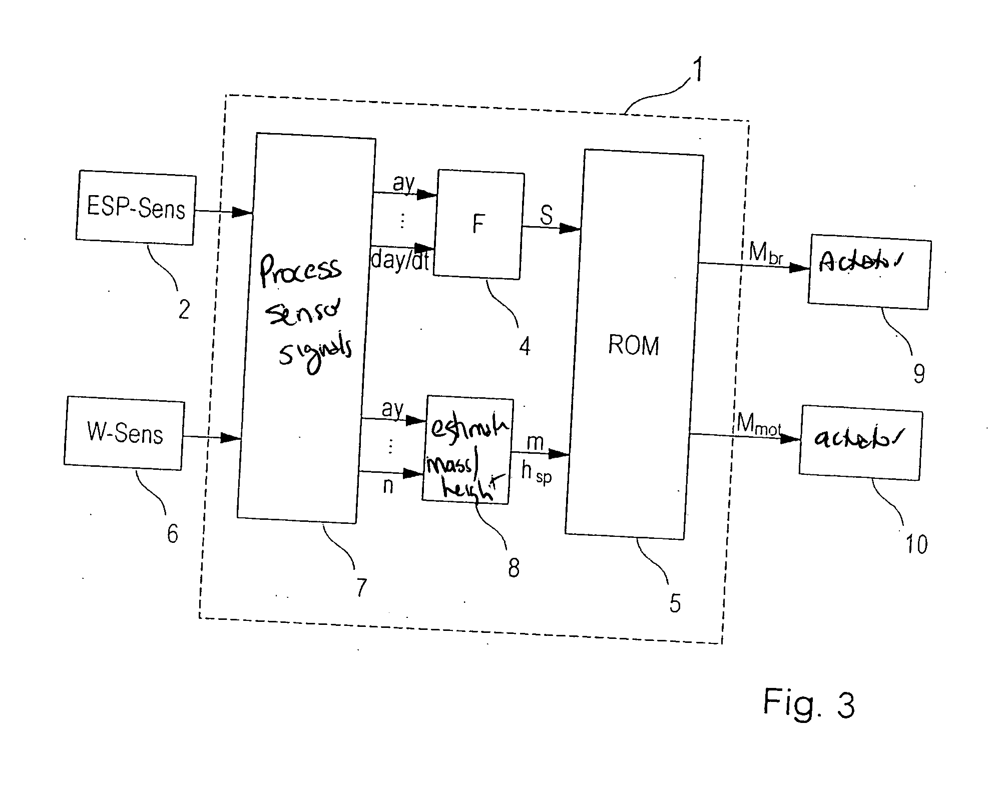
[0028]FIG. 3 shows a schematic block diagram of a rollover-stabilization system. The system includes a control unit 1 having a rollover-stabilization algorithm ROM (rollover mitigation), a sensor system 2, for measuring driving-condition variables, and various actuators 9, 10, with the aid of which the required stabilization interventions are implemented. Blocks 4, 7, 8 are implemented in the form of software and are used for processing the sensor signals (block 7), estimating the rollover tendency (by estimating the vehicle mass and the position of the center of gravity) of the vehicle (block 8), and generating an indicator variable S (block 4).

[0029] In this example, the rollover stabilization system utilizes exclusively ESP sensor system 2 that is already present, both for detecting a rollover-critical driving situation and for estimating vehicle mass m and the he...


PUM


Abstract

A method for rollover stabilization of a vehicle in critical driving situations, in which a rollover stabilization algorithm intervenes in the driving operation in a critical situation, using an actuator in order to stabilize the vehicle. Different loading states of the vehicle may be taken into consideration in that the vehicle mass as well as the characteristic speed and the ratio of the contact patch forces of the wheels are ascertained, and the rollover stabilization algorithm is executed as a function of the vehicle mass and the estimated vehicle center of gravity.

Description

FIELD OF THE INVENTION [0001] The present invention relates to a system and method for stabilizing a vehicle in a situation critical to rollover. BACKGROUND INFORMATION [0002] Vehicles having a high center of gravity, such as minivans, SUV's (sport utility vehicles), or vans, are prone to rolling over about the longitudinal axis, in particular when cornering at a transverse acceleration that is too high. For this reason, frequently rollover stabilization systems, such as ROM (rollover mitigation) are used, with the aid of which situations critical to rollover may be recognized early and stabilizing measures are able to be triggered. Conventional driving dynamics control systems, such as ESP, having a rollover stabilization function (ROM), usually intervene in the driving operation by way of the braking system, engine management or an active steering, so as to stabilize the vehicle. A conventional vehicle dynamics control system having an ROM function is shown by way of example in FI...

Claims


Application Information

Patent Timeline
IPC IPC(8): G06G7/76B60G17/016B60K28/10B60K28/14B60W10/04B60W10/18B60W30/02B60W30/04B60W40/12B62DB62D37/00
CPCB60G17/0162B60G2400/20B60G2400/30B60G2400/63B60G2800/9124B60T8/17554B60T2250/02B60W30/04B60W40/13B60W2040/1323B60W2530/20B60G2600/1877B60G2800/0124B60G2800/24B60G2800/70B60G2800/94B60K28/14B60W10/04B60W10/18B60W30/02B62D37/00B60G17/015B60G17/0165B62D17/00
Inventor NENNINGER, GERONIMMO, MATTHEWGRAF, GERALDBROOKS, LASZLO
Owner ROBERT BOSCH GMBH
Learn More