Super-resolution optical recording medium and method for recording information on super-resolution optical recording medium

Active Publication Date: 2007-04-12
TDK CORPARATION
View PDF5 Cites 8 Cited by
  • Summary
  • Abstract
  • Description
  • Claims
  • Application Information

AI Technical Summary

Benefits of technology

[0008] In view of the foregoing problems, various exemplary embodiments of this invention provide a super-resolution optical recording medium which can further increase its recording density and a method for recording information on the super-resolution optical recording medium.
[0009] As a result of diligent study, the inventor found that in a super-resolution optical recording medium, recording marks are formed in such a manner that at least a minimum recording mark in a modulation signal in an AFM (atomic force microscope) image (the image can be observed on a surface when a light transmission layer is removed) in a plan view takes the shape of a convex arc on the leading edge and the shape of a concave arc on the trailing edge, and this makes it possible to record information at a high CNR (carrier to noise ratio).
[0017] According to the present invention, the leading edge of at least the minimum mark of the recording marks in the modulation signal takes the shape of a convex arc and the trailing edge thereof takes the shape of a concave arc in the AFM image in a plan view. Therefore, it is possible to further improve recording density while maintaining a high CNR.

Problems solved by technology

Thus, reducing the wavelength λ and / or increasing the numerical aperture NA reduces the resolution limit, and hence increases recording density.

Method used


Image

  • Super-resolution optical recording medium and method for recording information on super-resolution optical recording medium
  • Super-resolution optical recording medium and method for recording information on super-resolution optical recording medium
  • Super-resolution optical recording medium and method for recording information on super-resolution optical recording medium

Examples


example 1

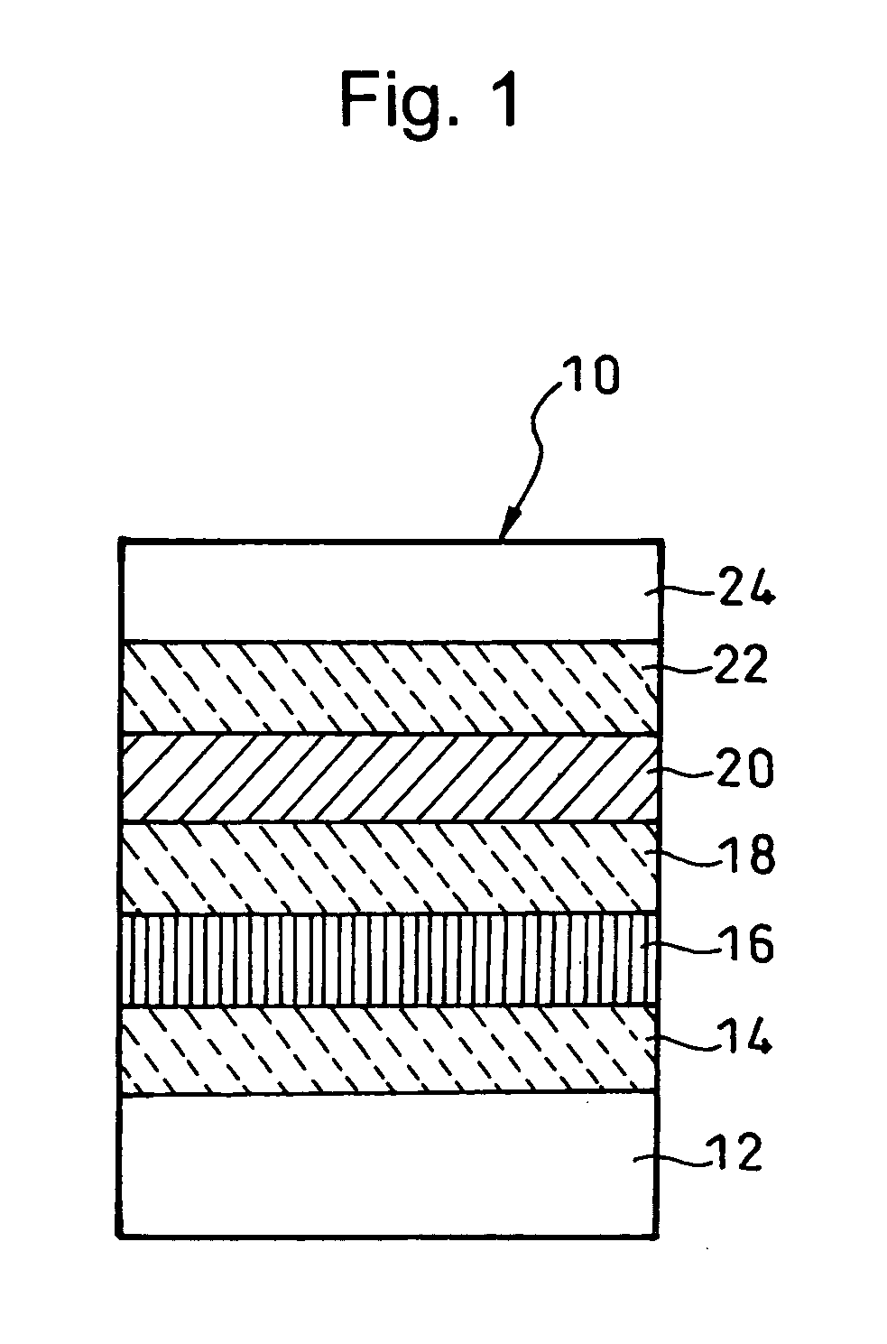
[0045] A super-resolution optical recording medium of Example 1 includes an Ag-alloy film with a thickness of 40 nm, a third dielectric layer made of ZnS:SiO2=85:15 with a thickness of 80 nm, a super resolution layer made of Sb75Te25 with a thickness of 10 nm, a second dielectric layer made of ZnS:SiO2=85:15 with a thickness of 40 nm, a recording layer made of PtOx with a thickness of 4 nm, a first dielectric layer made of ZnS:SiO2=85:15 with a thickness of 90 nm, and a light transmission layer with a thickness of 0.1 mm, and these layers are laminated in this order on a polycarbonate substrate.

[0046] In the medium having such a configuration, it is conceivable that the PtOx (recording layer) is decomposed into Pt and O2 by recording operation to form the recording marks with the volume change (deformation in the thickness direction), and the optical change of Sb75Te25 (super resolution layer) makes the reproduction of the recording marks with the size of the resolution limit or le...

example 2

[0052] A super-resolution optical recording medium of Example 2 includes an Ag-alloy film with a thickness of 40 nm, a third dielectric layer made of ZnS:SiO2=85:15 with a thickness of 80 nm, a super resolution layer made of Sb58Te42 with a thickness of 15 nm, a second dielectric layer made of ZnS:SiO2=85:15 with a thickness of 45 nm, a recording layer made of PtOx with a thickness of 4 nm, a first dielectric layer made of ZnS:SiO2=85:15 with a thickness of 45 nm, and a light transmission layer with a thickness of 0.1 mm, and these layers are laminated in this order on a PC substrate. When the recording marks were successively formed with varying the write power in stages as in the case of the Example 1, the shape of the recording mark at the maximum CNR in reproduction was the almost same as that of the Example 1. Deformation was observed by the AFM when CNR>35 dB.

[0053] In the above embodiments and examples, the light transmission layer 22 was peeled away from the super-resolutio...


PUM


Abstract

A super-resolution optical recording medium has at least a recording layer and a super resolution layer on a substrate. In the recording layer, a minimum recording mark is formed with spaces within a beam spot of a laser beam in recording. The minimum recording mark has a size of a resolution limit of a reproduction optical system or less, and can be reproduced by the reproduction optical system due to the existence of the super solution layer. The minimum recording mark in an AFM image takes the shape of a convex arc on a leading edge thereof and the shape of a concave arc on a trailing edge thereof (the AFM image is a plan view which can be observed on a surface when the light transmission layer is removed), and spaces have the similar shape to these.

Description

BACKGROUND OF THE INVENTION [0001] 1. Field of the Invention [0002] The present invention relates to a super-resolution optical recording medium which can reproduce information by irradiating reproduction light on recording marks formed on a recording layer. In particular, the present invention relates to the super-resolution optical recording medium from which small recording marks the size of which is equal to, or less than, the resolution limit of a reproduction optical system can be reproduced, and a method for recording information on the super-resolution optical recording medium. [0003] 2. Description of the Related Art [0004] In recent years, as described in, for example, Japanese Patent Laid-Open Publication No. 2003-6872, a super-resolution optical recording medium has been proposed, from which a recording mark train smaller than the diffraction limit of a reproduction optical system can be reproduced. [0005] In the case of a conventional optical recording medium, in genera...

Claims


Application Information

Patent Timeline
IPC IPC(8): G11B9/00
CPCG11B7/24
Inventor KIKUKAWA, TAKASHIFUKUZAWA, NARUTOSHIKOBAYASHI, TATSUHIRO
Owner TDK CORPARATION
Why Eureka
Try Eureka