Ball endmill

a ball endmill and ball end technology, applied in the field of ball endmills, can solve the problems of inability to improve cutting efficiency, inability to increase feed rate and cut depth, etc., and achieve the effect of restrainting and reducing the vibration of the ball endmill

Active Publication Date: 2007-04-12
OSG
View PDF6 Cites 9 Cited by
  • Summary
  • Abstract
  • Description
  • Claims
  • Application Information

AI Technical Summary

Benefits of technology

[0008] In the ball endmill defined in claim 1, each of the ball-nosed end cutting edges includes the first and second portions having the respective first and second radii of curvature which are different in value from each other. This construction causes a cutting resistance (cutting torque) exerted by a workpiece, to radially act in a direction that is different in the first and second portions of each ball-nosed end cutting edge, thereby making it possible to restrain vibration of the ball endmill.
[0009] That is, the direction in which the cutting resistance (cutting torque) is exerted by the workpiece on the ball endmill corresponds to a direction along each ball-nosed end cutting edge, i.e., a direction tangential to a circular arc defining each ball-nosed end cutting edge. Therefore, where the radius of curvature of each ball-nosed end cutting edge is constant from the inner peripheral portion up to the outer peripheral portion of the ball-nosed end cutting edge, as in the conventional ball endmill, the direction of the cutting resistance (cutting torque) does not substantially differ in the inner and outer peripheral portions of the ball-nosed end cutting edge, thereby easily causing the ball endmill to be vibrated.
[0010] On the other hand, in the ball endmill of the present invention, it is possible to cause the direction of the cutting resistance (cutting torque) exerted by the workpiece, to differ in the first and second portions of each ball-nosed end cutting edge, thereby making it possible to restrain vibration of the ball endmill. Owing to the reduction in the vibration, the feed rate and the depth of cut can be increased whereby the cutting efficiency can be improved.
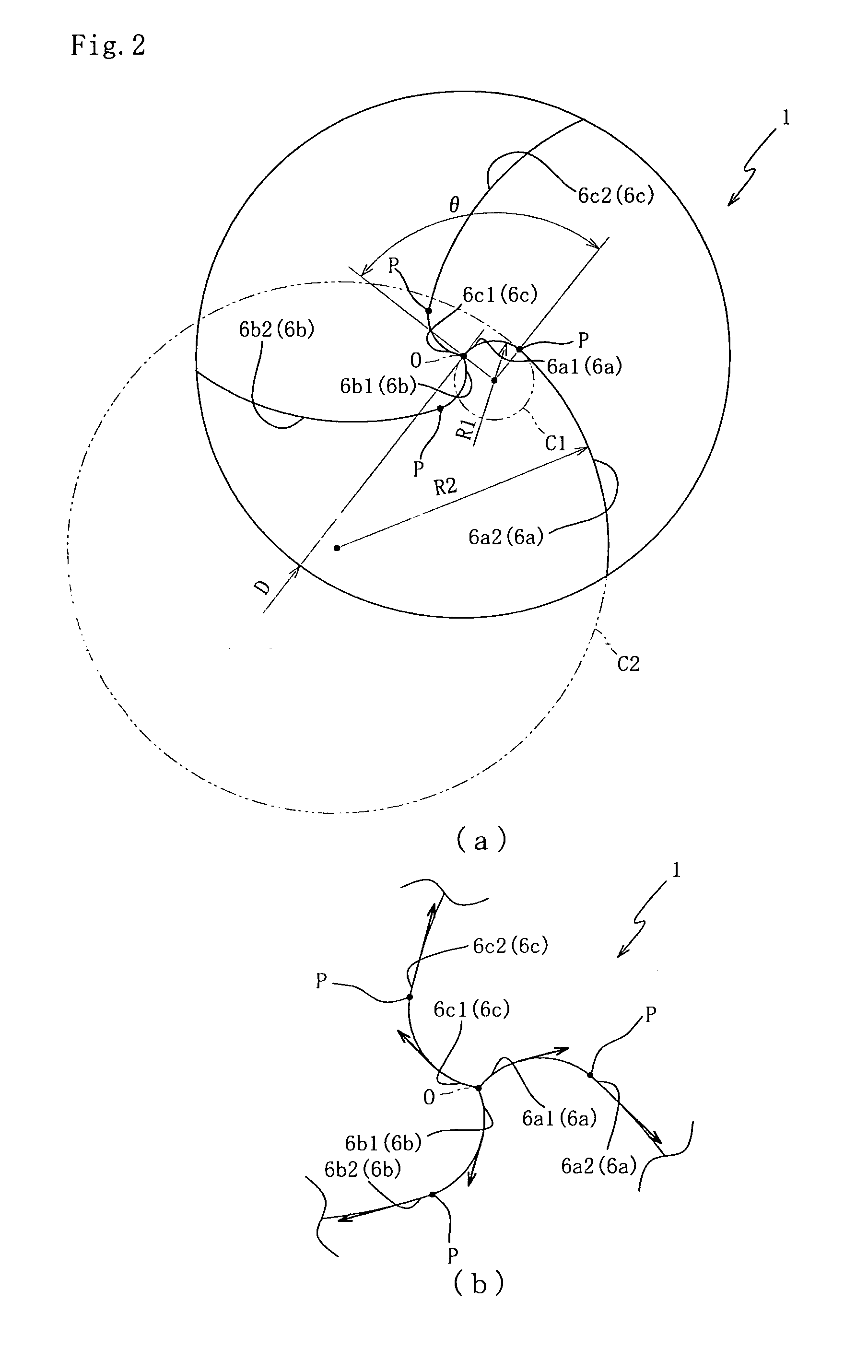
[0011] Further, in the ball endmill of the present invention, the first radius of curvature is in the range of from 0.025D to 0.10D relative to the outside diameter D. If the first radius of curvature is smaller than 0.025D relative to the outside diameter D, a spacing gap between the first portions of the adjacent ball-nosed end cutting edges in vicinity of the axis of the ball endmill is reduced whereby performance of evacuation of cutting chips is reduced. On the other hand, in the ball endmill of the present invention in which the first radius of curvature is not smaller than 0.025D relative to the outside diameter D, the spacing gap between the first portions can be sufficient for improving the performance of evacuation of cutting chips.
[0012] Further, in the case where the first radius of curvature is smaller than 0.025D relative to the outside diameter D, the spacing gap between the first portions of the adjacent ball-nosed end cutting edges in vicinity of the axis of the ball endmill is reduced. The reduction of the spacing gap, when each ball-nosed end cutting edge is ground by a grinding wheel in a grinding step, could cause the grinding wheel to interfere with the adjacent ball-nosed end cutting edge. On the other hand, in the ball endmill of the present invention in which the first radius of curvature is not smaller than 0.025D relative to the outside diameter D, the spacing gap between the first portions can be sufficient for preventing the interference of the grinding wheel with the adjacent ball-nosed end cutting edge. Thus, it is possible to eliminate necessity of an excessively highly accurate control in the grinding step, leading to reduction in cost for machining the ball endmill.
[0013] Where the above-described interference of the grinding wheel could be caused, there is a limitation in designing configuration of a portion that could suffer from the interference (for example, an elimination of such a portion could result in reduction of strength). In this sense, the sufficient spacing gap between the first portions, which prevents the interference of the grinding wheel, is effective to increase a degree of freedom in designing.

Problems solved by technology

Due to such a problem, the feed rate and the depth of cut can not be increased whereby the cutting efficiency can not be improved.

Method used


Image

  • Ball endmill
  • Ball endmill
  • Ball endmill

Examples


Embodiment Construction

[0026] Hereinafter, a preferred embodiment of the present invention will be described with reference to the drawings. View (a) of FIG. 1 is a front elevational view of a ball endmill 1 according to the embodiment of the invention, and view (b) of FIG. 1 is an enlarged side view showing in enlargement the ball endmill 1 as seen in a direction indicated by arrow Ib in view (a) of FIG. 1.

[0027] The ball endmill 1 is of solid type, and is a tool that is to be used principally for the purpose of performing an operation to machine a free-form surface of a die or mold. In the machining operation, a rotational force of a machine tool such as a machining center is transmitted to the ball endmill 1 via a holder (not shown) that is provided to hold a portion (a right side portion as seen in view (a) of FIG. 1) of a tool body 2 of the ball endmill 1.

[0028] The tool body 2 is constituted by cemented carbide alloy that is obtained by pressure sintering of tungsten carbide (WC) or the like. The ...


PUM


Abstract

A ball endmill having (a) a cylindrical tool body and (b) ball-nosed end cutting edges each of which includes (b-1) a first portion provided by a radially inner portion of each ball-nosed end cutting edge, and (b-2) a second portion provided by a radially outer portion of each ball-nosed end cutting edge. The first portion is defined by a circular arc which is convex in a direction of rotation of the tool body and which has a first radius of curvature as measured in a distal end view perpendicular to the axis. A ratio of the first radius of curvature to an outside diameter of the cylindrical body is not smaller than 0.025 and not larger than 0.10. The second portion is defined by a circular arc which is convex in the direction of the rotation of the tool body and which has a second radius of curvature as measured in the distal end view. The second radius of curvature is larger than the first radius of curvature.

Description

TECHNICAL FIELD [0001] The present invention relates to a ball endmill, and more particularly to such a ball endmill that is capable of restraining its vibration thereby permitting a cutting operation to be performed at an increased feed rate with an increased depth of cut and leading to an improvement in efficiency of the cutting operation. BACKGROUND ART [0002] For machining a die or mold, there is often used a ball endmill having ball-nosed end cutting edges in its axially distal end portion. Conventionally, in such a ball endmill, each of the ball-nosed end cutting edges has an arcuate shape that is convex in a direction of rotation of the ball endmill for the purpose of improving its cutting performance. It is common that a radius of curvature of each arcuate-shaped ball-nosed end cutting edge is adapted to be constant from its inner peripheral portion to its outer peripheral portion (for example, see Patent Document 1). Patent Document 1: JP-H04-51928Y2 DISCLOSURE OF INVENTIO...

Claims


Application Information

Patent Timeline
Patent Type & Authority Applications(United States)
IPC IPC(8): B23C5/10
CPCB23C5/1009B23C2210/084Y10T407/1924Y10T407/1948B23C2210/202
Inventor OSAWA, JIROHAMATAKE, YASUOAOKI, WATARU
Owner OSG
Why Eureka
Try Eureka