

Resin coating method, insert molding, and resin-coated metal gears
a technology of resin coating and metal gears, which is applied in the direction of gearing details, coupling device connections, other domestic articles, etc., can solve the problems of cracks or breaking fractures that are liable to occur in the insert molding, the resin layer is liable to peel in the molding, and the limited use of resin coatings, etc., to achieve excellent noise reduction properties
- Summary
- Abstract
- Description
- Claims
- Application Information
AI Technical Summary
Benefits of technology
Problems solved by technology
Method used
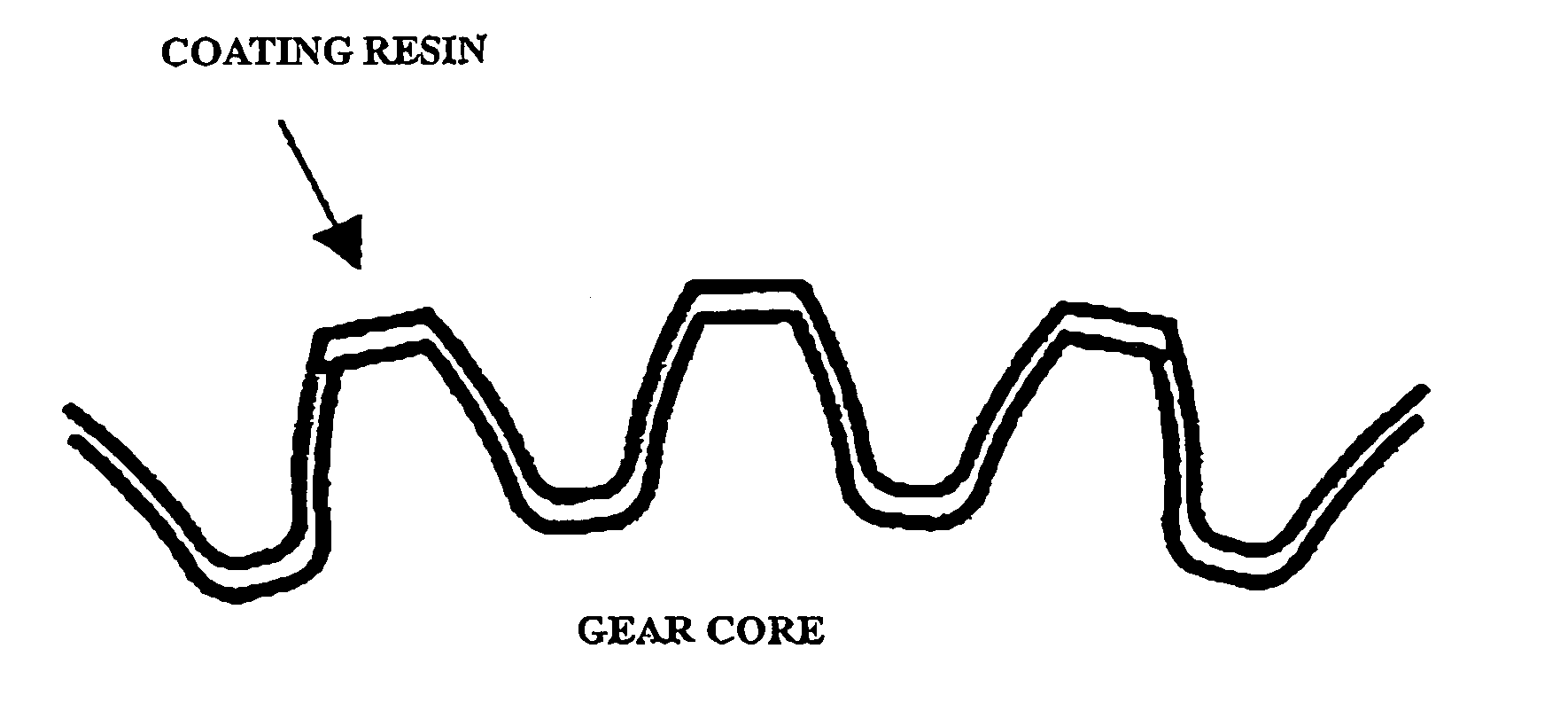
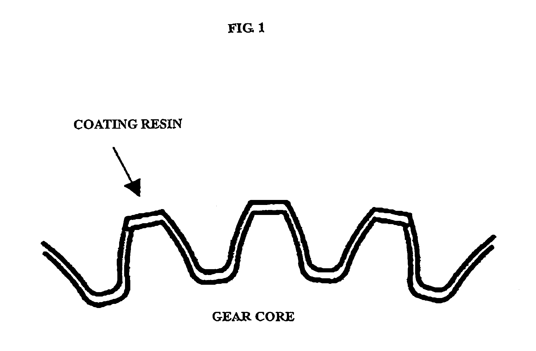
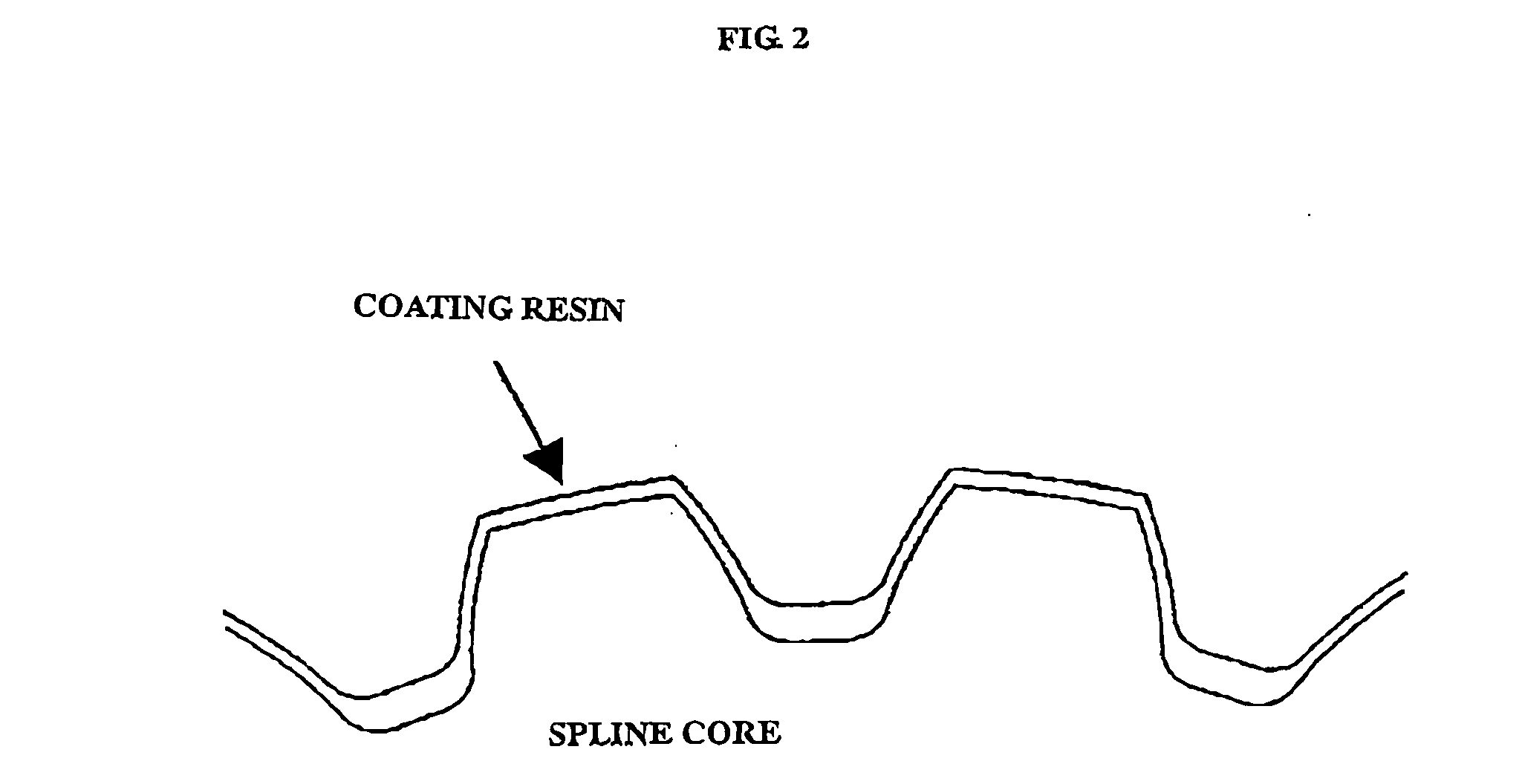
Image

Examples
example 1
[0111] A molten NORYL GTX resin (NORYL GTX 6601, a product of GE Plastics) of 290° C. was injected at a surface temperature of a shot blast-treated insert member of 230° C. and a mold temperature of 80° C. Thereafter, the resin was held under a pressure of 100 kgf / cm2 for 1 minute, and the resulting molding was taken out of the mold. The molding was gradually cooled to room temperature over 30 minutes. As shown in Table 1, the molding obtained did not generate cracks in the coated resin even after passing 7 days or more at room temperature. As a result of conducting the heating and cooling test, resin crack did not occur in all the moldings. Further, peel stress of the coating resin after the heating and cooling test was from 0.4 kgf / mm2 to 0.7 kgf / mm2. This is a value of the state that the insert member and the resin are sufficiently close-contacted, and shows that the molding obtained under this condition can use in air involving severe temperature change.
example 2
[0112] Molding was conducted in the same manner as in Example 1, except that the mold temperature was 140° C., the molten resin temperature was 270° C., the holding pressure was 300 kgf / cm2, and the cooling time up to room temperature after taking the molding out of the mold was 1 hour. As shown in Table 1, the molding obtained did not generate cracks in the coated resin even after passing 7 days or more at room temperature. Further, resin crack did not occur in all the moldings that have been subjected to the heating and cooling test. Peel stress of the coating resin after the heating and cooling test was from 0.5 kgf / mm2 to 0.7 kgf / mm2. This is a value of the state that the insert member and the resin are sufficiently close-contacted, and shows that the molding obtained under this condition can use in air involving severe temperature change. The value of peel stress is superior to the case of Example 1, and it is seen that the mold temperature is more preferably 140° C. than 80° C...
example 3
[0113] Molding was conducted in the same manner as in Example 2, except that the mold temperature was 150° C. As shown in Table 1, the molding obtained did not generate cracks in the coated resin even after passing 7 days or more at room temperature. Resin crack did not occur even in the moldings after the heating and cooling test. Further, close contact properties were substantially the same result as in Example 2. It was seen that although molding was conducted by elevating the mold temperature to a temperature 10° C. higher than the case of Example 2, there was almost no difference in performance of the molding.
PUM
| Property | Measurement | Unit |
|---|---|---|
| temperature | aaaaa | aaaaa |
| temperature | aaaaa | aaaaa |
| thickness | aaaaa | aaaaa |
Abstract
Description
Claims
Application Information