Method for reduced-artifact radiological 3D imaging, medical imaging device and method for creating a therapy plan

Inactive Publication Date: 2007-04-12
SIEMENS AG
View PDF5 Cites 27 Cited by
  • Summary
  • Abstract
  • Description
  • Claims
  • Application Information

AI Technical Summary

Benefits of technology

[0008] An advantage of the invention lies in the fact that the determination of HU values of the tissue of the patient is improved. I.e. the regions of an image data set affected by artifacts are reduced in their extent compared to conventional 3D image data sets. This has the effect in therapy planning of improving the extent calculation and thereby of increasing the precision in the irradiation. In diagnostics, because of the reduction of metal artifact-affected regions, anatomical areas which were not previously visible because of the artifacts can be assessed.
[0009] In one embodiment of the invention obtaining the data of an object to be scanned is undertaken with two or more imaging steps which have different tilt settings of a CT gantry. In the different imaging processes the artifact-affected regions are formed in different spatially arranged radiographic layers. In addition to a tilting, movement or turning of the CT gantry for example (in general of the imaging device) the object under investigation to be scanned can also be moved, turned or tilted relative to the CT device for example. The latter also causes a change to the artifact-affected regions in the imaging volume.
[0010] In a method of this type the area which can no longer be constructed because of for example the complete absorption of the x-ray radiation lies at different positions in the different reconstructions; i.e., different raw data or image data elements are affected by the interfering elements. With this data the areas which have been affected by the interfering elements are defined in all reconstructed imaging volumes. Their relative position in relation to each other is known uniquely through the setting in

Problems solved by technology

Such interfering elements in the area of a patient to be examined radiographically thus cause the loss of evaluable projection data.
This means that the reconstruction of an image data set from such

Method used


Image

  • Method for reduced-artifact radiological 3D imaging, medical imaging device and method for creating a therapy plan
  • Method for reduced-artifact radiological 3D imaging, medical imaging device and method for creating a therapy plan
  • Method for reduced-artifact radiological 3D imaging, medical imaging device and method for creating a therapy plan

Examples


Example

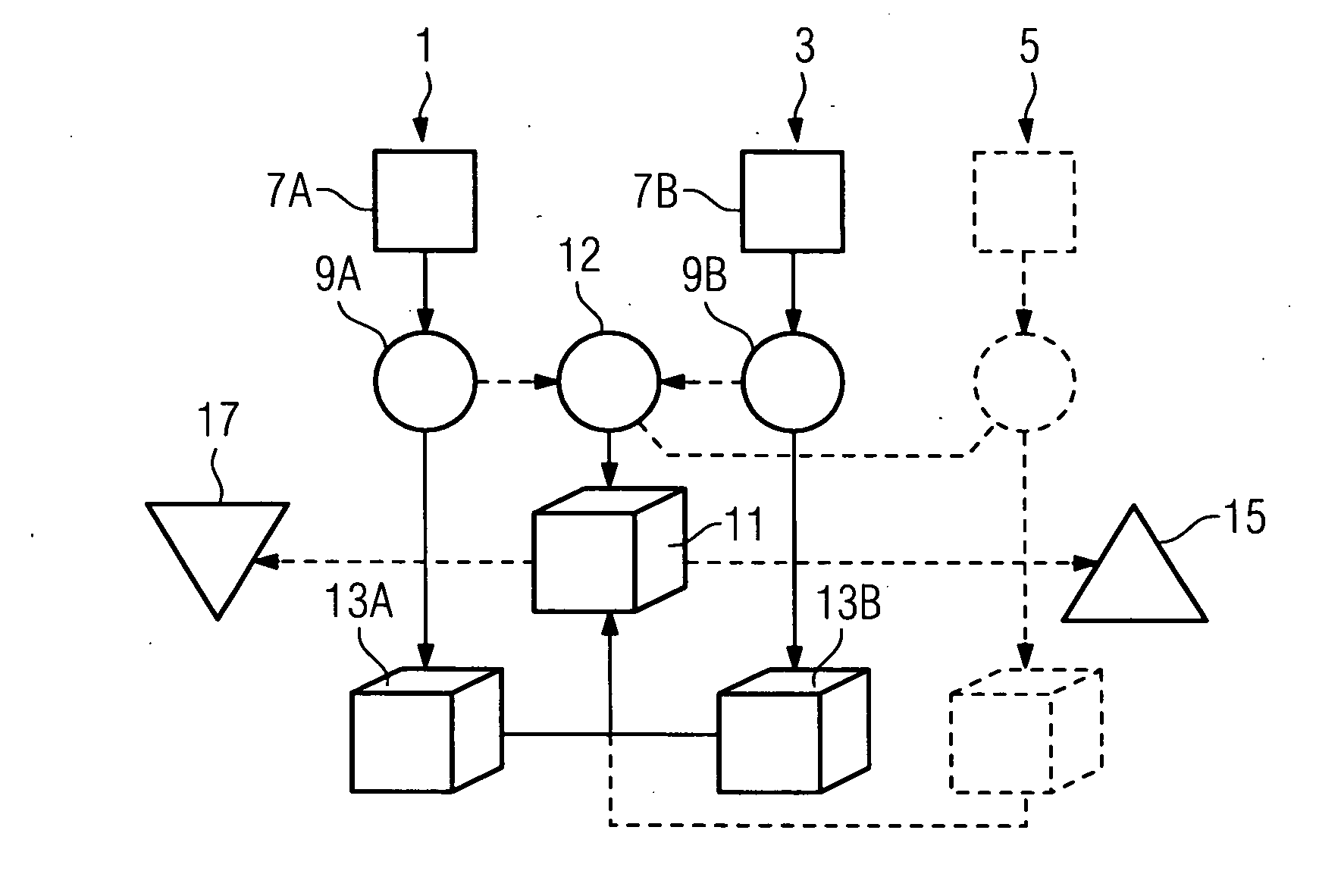
[0020]FIG. 1 shows a typical schematic flow diagram to illustrate the procedure for generating reduced-artifact image data. The method is illustrated on the basis of two imaging procedures 1 and 3, in which case further imaging procedures 5 (as shown by dashed lines) can also be included. Each of the imaging procedures 1,3, 5 begins with a positioning process in which a patient is positioned in a first imaging position 7A or a second imaging position 7B within an imaging device (for an illustration see FIG. 2 with associated description). 3D-imaging is performed in each of the imaging positions 7A, 7B in which a set of radiographic layers are radiographically examined in each case with a radiographic source and are recorded positionally-resolved by a radiation detector. This creates a first raw data record 9A or a second raw data record 9B and this is prepared for further processing. The decisive point is now that the imaging positions 7A and 7B differ from each other in their geome...


PUM


Abstract

The invention relates to a method for reduced-artifact 3D-imaging of an imaging volume comprising an interfering element a patient is positioned in a first and second positions spatially different from each other in an imaging device and a first and second 3D-imagings are performed with the interfering element lying within a first and second radiographic layer. A first and second set of raw data of the imaging volume are provided with the first set having artifact-influenced raw data for the first radiographic layer and the second set having artifact-influenced raw data for the second radiographic layer and non-artifact influenced raw data for the first radiographic layer the reduced-artifact 3D data set is created By combining the raw data sets for calculating the reduced-artifact 3D data set or by calculating a first and second 3D image data sets from the raw data sets and combining the 3D image data sets.

Description

CROSS REFERENCE TO RELATED APPLICATIONS [0001] The present application claims the benefit of the provisional patent application filed on Sep. 16, 2005, and assigned application No. 60 / 717,831. The present application also claims priority of German application No. 10 2005 044 407.5 filed on Sep. 16, 2005. Both of the applications are incorporated by reference herein in their entirety.FIELD OF THE INVENTION [0002] The invention relates to a method for reduced-artifact radiological 3D imaging of an imaging volume of a medical imaging device, whereby the imaging volume features at least one interfering element causing an artifact. The invention further relates to a medical imaging device for creating a 3D radiological image data set as well as to a method for creating a therapy plan for irradiating a patient with particles of a particle therapy system. BACKGROUND OF THE INVENTION [0003] In radiological imaging with a computer tomography (CT) device for example, materials with high densi...

Claims


Application Information

Patent Timeline
IPC IPC(8): A61B5/05
CPCA61B6/032A61B6/12A61B6/4447A61B6/466A61N5/103G06T5/50G06T11/005G06T2200/04G06T2207/30004A61B6/5258
Inventor RIETZEL, EIKE
Owner SIEMENS AG
Why Eureka
Try Eureka