Apparatus & method for determining physiologic characteristics of body lumens

Inactive Publication Date: 2007-04-12
ANGIOMETRX
3 Cites 53 Cited by

AI-Extracted Technical Summary

Problems solved by technology

The accumulation of plaque narrows the interior passage, or lumen, of the blood vessels and in many cases impairs blood flow beyond the blockage.
Atherosclerosis in the coronary arteries, which carry oxygenated blood to the heart, results in chest pain, known as angina, and can ultimately lead to heart attack and death.
In peripheral arteries (the vascular system remote from the heart) atherosclerosis can lead to decreased mobility, chronic pain and amputation.
Such a measurement is typically not particularly accurate since it relies on discerning an ill-defined boundary in a single plane.
Additionally, stenotic material outside of the image plane can be missed.
These limitations with the radiographic image typically result in average errors of approximately 30%.
Such inaccuracy hinders adequate characterization of vascular disease.
Radiographic assessment of, e.g., stent expansion is subject to the above-described and additional errors that can further hinder the physician's ability to deliver adequate treatment to the patient.
W...

Benefits of technology

[0016] In some embodiments, the preselected pressure is below 300 mmHg. For example, where the body lumen is a coronary blood vessel, the preselected pressure is typically between 200 and 300 mm Hg. In other variations, where the body lumen is a non-vascular body lumen, the preselected pressure is typically less than one atmosphere. The method can also include determining medium volume for a plurality of medium pressures (e.g., a plurality of pressures below 300 mmHg).
[0017] Physiological characteristics of a body lumen that are particularly amenable to measurement using the method described herein include, for example, an internal dimension (such as, e.g., a cross-sectional area or an internal diamet...

Abstract

Disclosed are a system, apparatus, and method for determining a physiologic characteristic of a body lumen that include determining, at one or more selected pressures, the volume of incompressible medium infused into a balloon 54 of catheter 24 while the balloon is placed in each of (a) a lumen having a predetermined, fixed diameter and (b) a desired location of a body lumen having an unknown diameter. In certain variations, the physiologic characteristic (e.g., diameter, cross-sectional area) is determined by calculating the difference in the volume of infused medium between (a) and (b) at at least one static pressure. Other physiologic characteristics (e.g., compliance) are determined by calculating the difference in infused medium for (b) at at least two static pressures.

Application Domain

StentsMedical devices +4

Technology Topic

Catheter device

Image

  • Apparatus & method for determining physiologic characteristics of body lumens
  • Apparatus & method for determining physiologic characteristics of body lumens
  • Apparatus & method for determining physiologic characteristics of body lumens

Examples

  • Experimental program(3)

Example

EXAMPLE 1
[0110] Measured area using Equation 8=2.63 mm2. Since 2.23<2.63<3.0, the first set of the linear coefficients is used to calculate the actual area as shown below: Actual ⁢ ⁢ hole ⁢ ⁢ size = m 1 · A c + b 1 Actual ⁢ ⁢ Hole ⁢ ⁢ size = 0.820 · 2.63 ⁢ ⁢ mm 2 + 0.171 ⁢ ⁢ mm 2 = 2.32 ⁢ ⁢ mm 2

Example

EXAMPLE 2
[0111] Measured area using Equation 8=3.66 mm2. Since 3.45<3.66<4.11, the second set of linear coefficients is used to calculated the actual area as shown below: Actual ⁢ ⁢ hole ⁢ ⁢ size = m 2 · A c + b 2 Actual ⁢ ⁢ Hole ⁢ ⁢ size = 1.52 · 3.66 ⁢ ⁢ mm 2 - 2.24 ⁢ ⁢ mm 2 = 3.32 ⁢ ⁢ mm 2
[0112] Linear equations can be used for each of the calibration and measurement cycles to filter any noise from fluctuations of body lumen pressure (e.g., systolic and diastolic blood pressure fluctuations). Accordingly, in certain variations, the system scans and stores the pressure for every step (volume) that is infused into the catheter, and, by using linear regression analysis, the data is used to filter any noise that the body pressure effect may have on the balloon pressure. For example, a linear equation that may be used to filter body pressure fluctuations is as follows:
Linear equation: Vn=mPn+b (Equation 9)
[0113] where: [0114] m is the slope [0115] b is the offset [0116] Vn is the set of infused volume data [0117] Pn is the set of pressure reading data [0118] Vave is the mean infused volume [0119] Pave is the mean pressure reading m = ∑ n 1 ⁢ ( P n - P ave ) · ( V n - V ave ) ∑ P n - P ave b = V ave m · P ave
[0120] Using Equation 9, volume can be calculated at a given measurement pressure, which is then used to calculate, for example, the actual area and diameter of the blood vessel as set forth further herein.
[0121] Further, a coefficient of determination (R2) shows how scattered the data points are around the P/V line and can be used in both the calibration sequence and measurement sequence to determine whether the P/V line is valid: R 2 = ∑ n 1 ⁢ ( V n - V ave ) 2 - ( ⁢ m 2 · ∑ n 1 ⁢ ( P n - P ave ) 2 ( N - 2 ) ( Equation ⁢ ⁢ 10 )
If the blood pressure of the patient is too high or there is ambient noise in the system that prevents a suitable clean set of pressure data from being acquired, (e.g. other noise in the signal such as that due to motion artifact, which might prevent accurate measurements from being made), the R2 value will be low and a valid measurement cannot be made. Accordingly, in certain embodiments, the system can be configured to produce an error state in which the user is alerted that the blood pressure of the patient is too high.
[0122] Actual blood vessels, of course, are typically compliant to some extent. If vessels are investigated in vivo using the system of the present invention, the cross-sectional area of the vessel would increase slightly following the infusion of additional fluid beyond that necessary to just produce contact between the balloon and the interior surface of a vessel. The change in cross-sectional area with an increase in pressure is a measure of vessel compliance or elasticity. The present invention can thus not only produce an accurate result for cross-sectional area, but also provide direct, in vivo information on vessel compliance as well.
[0123] Thus, measuring the diameter at two different inflation pressures provides a measurement of compliance. In accordance with the present invention, compliance can be expressed as the relationship between the amount of volume infused and the pressure that is needed to infuse the extra fluid in order to expand the artery. This requires expanding the artery where it is contacted by the balloon to above its nominal size, typically by a very small amount. The following equation is particularly suitable for determining compliance using the methods provided herein: C = A 2 - A 1 A 1 · ( P 2 - P 1 ) · 100 ⁢ %
where: [0124] C is the percentage of compliance of the constrained artery for every change in pressure (P2-P1) [0125] A1 is the area measured at P1 [0126] A2 is the area measured at P2 [0127] P1 is low pressure where the balloon is touching the artery wall (e.g., 220 mmHg) [0128] P2 is high pressure where the balloon is slightly flex the artery wall (e.g., 260 mmHg).
[0129] Compliance can be expressed graphically by plotting infused volume against pressure. In this case, compliance (being the overall compliance of the measurement system, which is the sum of the compliance of the catheter system, including the balloon and the inflation fluid and the compliance of the restraining lumen) is represented as the slope of the pressure/volume curve. This can be seen graphically in FIG. 12, showing the slopes of a calibration curve 130 (with the balloon in a fixed lumen of known diameter) and of a measurement curve 132 (with the balloon in a body lumen). FIG. 12 indicates points on each of curves 130 and 132 corresponding to a first volume V1 at a first pressure P1 and a second volume V2 at a second pressure P2. Compliance of catheter system while in the calibration lumen is represented as ΔV130/ΔP, while the compliance of the catheter system while in the body lumen is represented as ΔV132/ΔP.
[0130] In determining the compliance of a body lumen, the compliance of the calibration curve is typically taken as 0 compliance (the natural compliance of the catheter system). This compliance is a function of, for example, the materials of the catheter as well as the volume of any compressible medium (e.g., gas bubbles in the fluid) within the catheter. Accordingly, the calibration curve compliance typically depends of the specific catheter being used, on the fluid being used in the preparation (e.g., the amount of small air bubbles in the fluid), and if any small amounts of air is left in the catheter after preparation. The compliance of the body lumen (e.g., blood vessel) is calculated as the change in slope of the curve compared to the calibration slope.
[0131] The present system for determining compliance in which calibration is performed with the balloon in a fixed lumen of known diameter, provides a better means for accurately determining compliance compared to previous method in which calibration is performed with the balloon unconstrained. The use of an unconstrained balloon for calibration accounted for balloon compliance in the calculation of body lumen compliance. However, the balloon when making a measurement within a body lumen does not typically stretch or expand. Using the methods provided herein, balloon elasticity is not accounted for, thereby addressing this deficiency in previous methods.
[0132] In certain embodiments of the present method, both the actual cross-sectional area and compliance of a body lumen are measured. In one specific variation, the calibration and measurement cycles include measuring infused volume at a pressure that will be used to calculate the actual cross-sectional area of the body lumen (the “measurement pressure”); a pressure that is below the measurement pressure (the “low pressure”); and a pressure above the measurement pressure (the “high pressure,” typically just slightly above the measurement pressure). For example, in some embodiments for measuring characteristics of a blood vessel, suitable pressures include, e.g., a measurement pressure of 250 mmHg, a low pressure of 200 or 220 mmHg, and a high pressure of 260 mmHg. Measured volumes at the low and high pressures are used to calculate a change in area for determining compliance.

Example

EXAMPLE
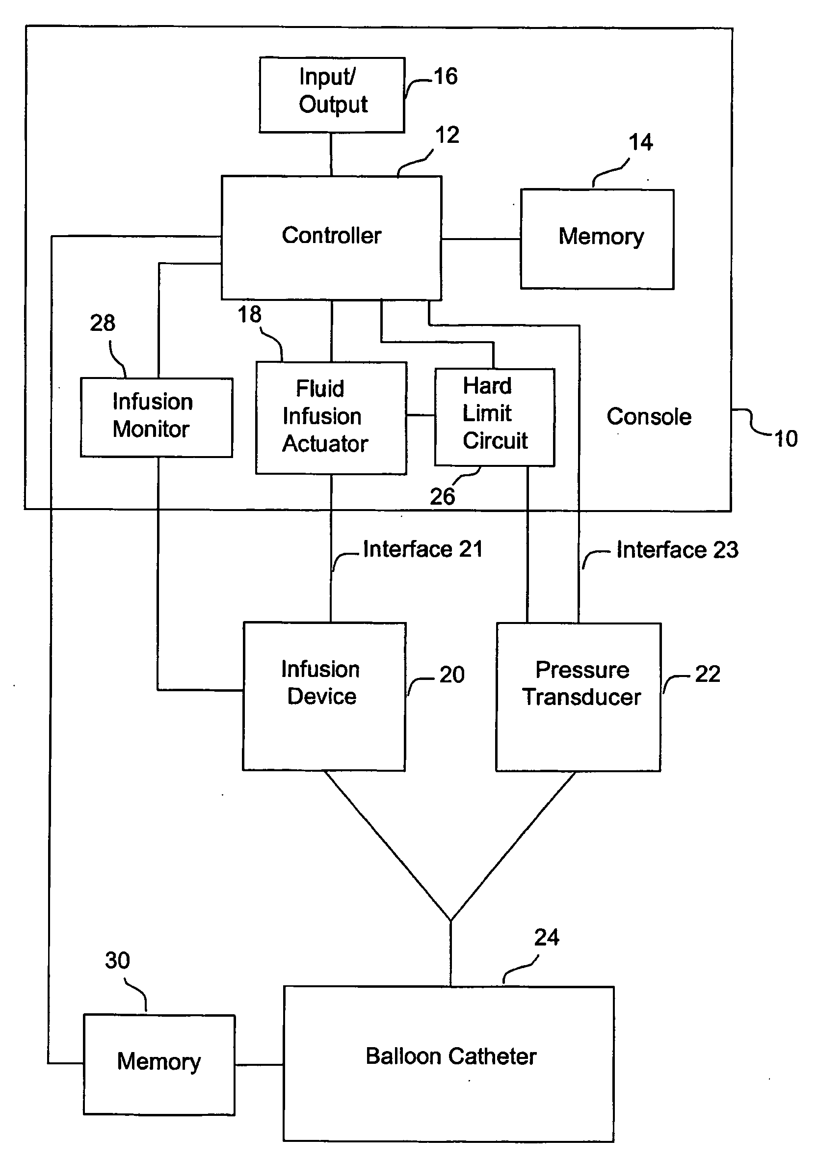
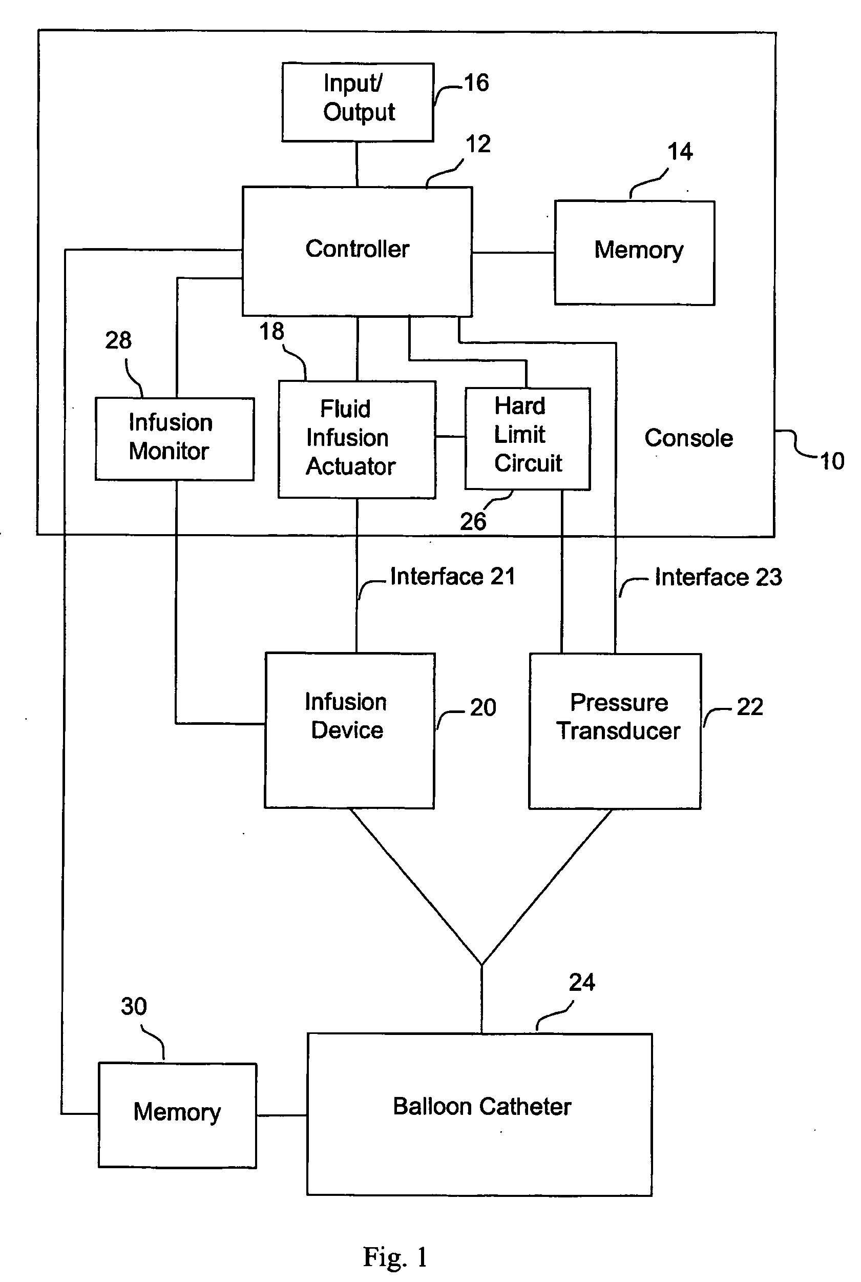
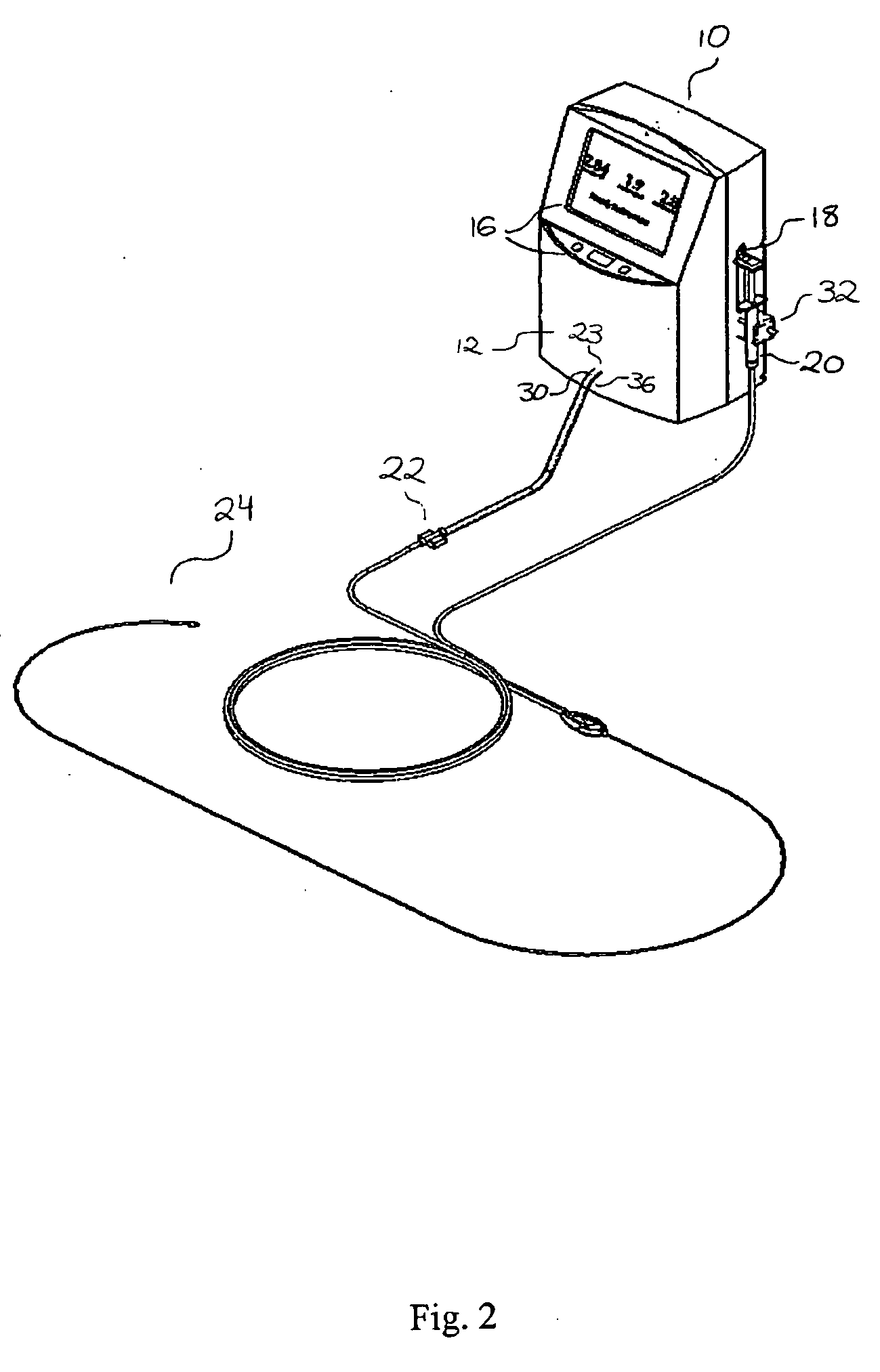
[0133] One specific method of the present invention proceeds as follows. Balloon catheter 24 is purged of all air with a non-compressible fluid (e.g., saline), and balloon 54 of the catheter is placed in a lumen having a predeterminted, fixed diameter. Fluid is infused into the catheter through inflation lumen 66 as described above. Pressure transducer 22, which is in fluid communication with pressure lumen 68, produces a signal indicative of the pressure in pressure lumen 68 that represents the static pressure in the balloon. As noted above, both the fluid infusion actuator 18 and the pressure transducer 22 are in communication with controller 12, which measures infused fluid volume at one or more predetermined pressure values. A typical range of pressure values is 200-300 mmHg. The deflated balloon catheter is then positioned in a body lumen to be measured (such as, e.g., a blood vessel, the intestine, or the urethra), and the balloon 54 manipulated to the point of interest. Typically, this is accomplished by feeding the catheter over a guidewire which has been previously placed in the body for this purpose; in this case, the balloon catheter includes along its length dedicated guidewire lumen 64, separate from the fluid inflation and pressure monitoring lumens (see, e.g., FIG. 6), to facilitate this process. The infused fluid volume is then measured at the same predetermined pressure value(s). In each case, fluid is infused into the balloon in accordance with a predetermined rate schedule involving known fluid infusion rate amounts at specific pressure intervals. The vessel cross-sectional area is calculated using equation 7, either after each pressure-volume measurement or after all the pressure-volume measurements have been made. The ideal pressure for measurement will vary according to the body lumen being measured, but typically the ideal pressure is relatively low and usually does not exceed one atmosphere. In certain embodiments directed toward measurement of arterial vessels, the infused volume is determined at a pressure of approximately 250 mm Hg, which is the typical peak pressure that might be observed in the vessel during physical exertion. Determination of infused volume at a single pressure value will provide the physiologically useful cross-sectional area information concerning the vessel, while a plurality of area determinations, at two or more pressures, will provide information on the compliance of the vessel.
[0134] In certain variations of the infusion process of the present invention, infusion of fluid into the balloon catheter proceeds as follows. Starting from a negative pressure in a catheter 24 which has been purged of substantially all air by filling it with a fluid such as saline, with the plunger 74 of the syringe 20 in the withdrawn position, the infusion actuator 18 begins infusion to inflate the balloon 54 by stepping the plunger forward into the syringe. While the controller 12 monitors each step of fluid infusion, movement of the plunger may be further verified by interrogating an optical sensor at each cycle of a predetermined number of steps to ensure that a change in position has occurred. After an initial, predetermined volume of fluid has been infused, controller 12 verifies that the transducer has sensed a predetermined minimum increase in pressure. During the calibration the controller 12 monitors pressure and volume relationships and checks for leaks in or kinking of the catheter and for proper functioning of the transducer. To ensure patient safety, if controller 12 senses a problem in either the optical position sensor or the pressure sensor (for example, if proper motion of the plunger is not observed or there has not been a proper increase in pressure within the balloon), then the stepper motor is immediately reversed to withdraw the plunger and remove the infused fluid. In certain variations, the controller 12 is placed in an error state, further operation is prevented, and the user is alerted.
[0135] For example, in one specific embodiment in which infusion syringe 20 is a calibrated 3 cc syringe, infusion pump 18 begins infusion starting from a negative pressure of −100 mm Hg. Movement of the plunger is verified at each cycle of 110 steps, corresponding to 0.1375 mm of linear movement of the syringe plunger. After infusion of 40 μl of fluid, corresponding to about 550 steps, controller 12 verifies that the transducer has sensed a minimum increase in pressure of at least a 5 mmHg.
[0136] Under normal operating conditions, when the initial position and pressure indicators are correct, the system continues to step the plunger forward infusing fluid and monitoring pressure at each step until the pressure at the transducer reaches a predetermined endpoint pressure slightly greater that the pressure measurement point, or until a predetermined endpoint total of fluid has been infused (e.g., 260 mmHg, 10 mmHg greater than a 250 mmHg measurement point, or a total of 160 μl of fluid). At either of these endpoints, the stepper motor is reversed and the fluid is withdrawn until the starting position of the plunger is reached.
[0137] In certain variations, the infused volume measurement(s) are used to calculate the cross-sectional area and then the calculated cross-sectional area is transformed using one or more linear equation(s) (see, e.g., Equation 8 and related description, supra) that are specific to the individual catheter connected to the computer controller. The transformed cross-sectional area results in the true measured cross-sectional area for the specific infused amount of volume for the specific balloon catheter used for the measurement.
[0138] The area and diameter calculations taken as a whole will show increases in area and diameter with increases in pressure. A plot of this information will show the compliance of the vessel, similar to the plot of volume vs. pressure shown in FIG. 12. As indicated above, and depicted graphically in FIG. 12, compliance may be represented as the difference between the measured volumes (V1 and V2) at at least two measured pressures (P1 and P2, respectively).
[0139] Hence, an accurate and fast apparatus and method has been described which provides size and compliance information for blood vessels. Further, the apparatus can be used to obtain similar information for other body members having an opening therein (some of which are tube-like), such as the intestines, the bronchia, the urethra, the cervix, etc. This information is particularly useful in the diagnosis of certain diseases affecting vessels and such body members. The accuracy of the apparatus and method exceeds significantly that of existing methods relative to size determination. The apparatus and method further provide compliance information which heretofore has not been available.
[0140] Although a preferred embodiment of the invention has been disclosed herein for illustration, it should be understood that various changes, modifications, and substitutions may be incorporated in such embodiment without departing from the spirit of the invention which is defined by the claims which follow. All publications, patents, and patent applications cited herein are hereby incorporated by reference in their entirety for all purposes.

PUM

no PUM

Description & Claims & Application Information

We can also present the details of the Description, Claims and Application information to help users get a comprehensive understanding of the technical details of the patent, such as background art, summary of invention, brief description of drawings, description of embodiments, and other original content. On the other hand, users can also determine the specific scope of protection of the technology through the list of claims; as well as understand the changes in the life cycle of the technology with the presentation of the patent timeline. Login to view more.
Why Eureka
Try Eureka