Solar photovoltaic output for cloudy conditions with a solar tracking system

a solar tracking and solar energy technology, applied in the field of terrestrial positioning of photovoltaic cells, can solve the problems of not being superior, relatively high investment cost per unit of required power, and the design and operation of a photovoltaic system, so as to reduce the size and cost of the pv power system as well as the physical space required. , to achieve the effect of maximizing the energy output of solar powered pv cells

Active Publication Date: 2007-04-19
GM GLOBAL TECH OPERATIONS LLC
View PDF13 Cites 112 Cited by
  • Summary
  • Abstract
  • Description
  • Claims
  • Application Information

AI Technical Summary

Benefits of technology

[0008] This invention provides a PV directional control method that is applicable to modules of a plurality of solar powered photovoltaic cells, especially modules with planar light-receiving surfaces. The method has general utility to maximize the energy output of solar powered PV cells, and it has particular utility where the module(s) is used to power an electrolyzer system to produce hydrogen a

Problems solved by technology

However, there is a challenge in the design and operation of a photovoltaic system because of the large variation in solar radiant flux density (irradiance) at virtually every location on the surface of the earth.
The planar module, or cluster of modules which is called an array, represen

Method used


Image

  • Solar photovoltaic output for cloudy conditions with a solar tracking system
  • Solar photovoltaic output for cloudy conditions with a solar tracking system

Examples


Embodiment Construction

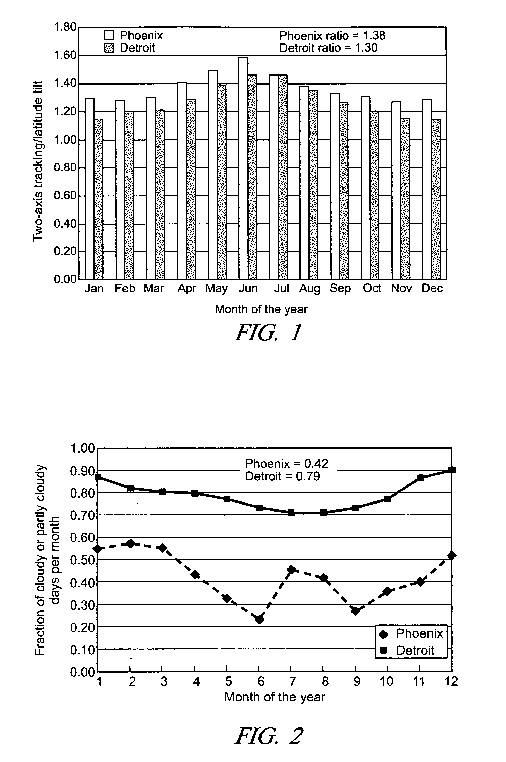
Expected PV Improvement with a Two-Axis Tracking System

[0019] The sun's location in the sky relative to a location on the surface of the earth can be specified by two angles: 1) the solar azimuth angle and the solar zenith angle. The solar azimuth angle is the location of the sun in the sky relative to a line running due north. An azimuthal angle of 180 degrees occurs when the sun is due south and defines solar noon at the location of interest. On a sunny day this will be the time of maximum solar insolation provided there are no clouds. By way of example, the solar insolation of a northern US location, Detroit, Mich. and a southern location, Phoenix, Ariz. will be considered and compared.

[0020] For Detroit, Mich. at the winter solstice, the sun rises in the eastern sky at 8 AM at an azimuthal angle of 120 degrees and sets in the western sky at 5:00 PM with an azimuthal angle of 238 degrees, moving only 118 degrees across the southern horizon. At the summer solstice in Detroit, t...


PUM


Abstract

An array of solar powered photovoltaic modules is optimally oriented and operated to provide more electrical energy for uses such as powering an electrolyzer system for hydrogen production. The array is positioned with its light receiving surface at an optimal angle, preferably a continually changing angle determined by two-axis solar tracking, when continually measured solar irradiance indicates suitable sunlight, and at a horizontal position when measured solar irradiance indicates excessive atmospheric cloudiness.

Description

TECHNICAL FIELD [0001] This invention pertains to the terrestrial positioning of modules of photovoltaic cells with respect to the sun. The invention is particularly concerned with efficient investment in photovoltaic modules and optimized use of such modules to provide electrical power, such as that for the electrolytic production of hydrogen from water. BACKGROUND OF THE INVENTION [0002] Photovoltaic (PV) cells are known semiconductor devices that convert light (i.e. by photons impinging on a pn junction) into electrical energy. Of course, sunlight can be used as the source of energy. Amorphous silicon, crystalline silicon, and selenium are examples of materials that are used in devising such cells. The voltage provided by an individual cell may be relatively small but many such cells can be combined as modules in electrical series and / or parallel connections to produce electrical power at voltage and current levels suitable for many applications. The modules are often constructed...

Claims


Application Information

Patent Timeline
IPC IPC(8): H02N6/00
CPCH01L31/042Y02E10/50Y02E10/47F24J2/38G01S3/7861H02S20/32F24S50/20H02S50/00
Inventor KELLY, NELSON A.GIBSON, THOMAS L.
Owner GM GLOBAL TECH OPERATIONS LLC
Why Eureka
Try Eureka