
Mass spectrometer

a mass spectrometer and mass spectrometer technology, applied in the field of mass spectrometers, can solve the problem that the method cannot provide information about the structure of such a large molecule, and achieve the effect of increasing the target mass

Inactive Publication Date: 2007-04-19
SHIMADZU CORP
View PDF4 Cites 26 Cited by
  • Summary
  • Abstract
  • Description
  • Claims
  • Application Information

AI Technical Summary

Benefits of technology

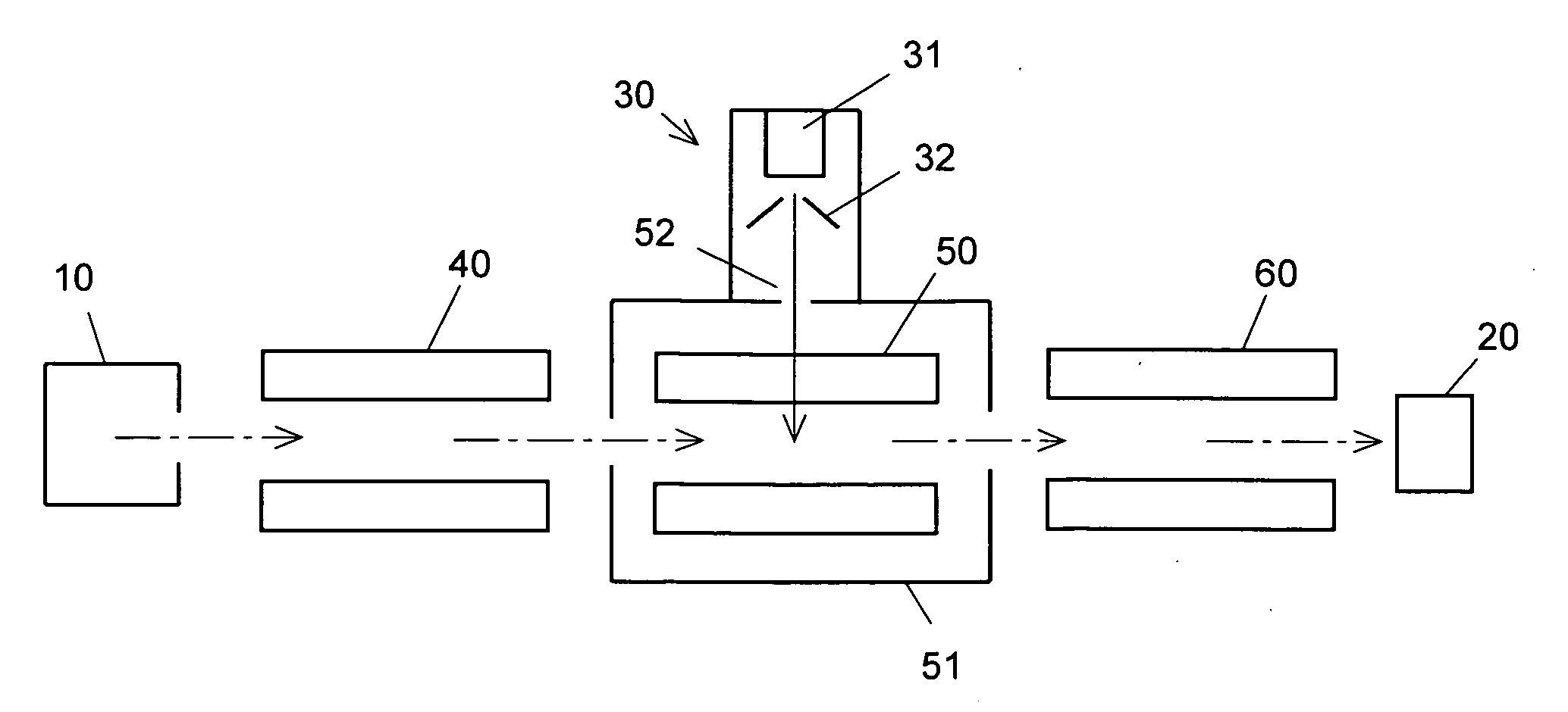
[0021] Having the construction described thus far, the mass spectrometer according to the present invention uses a cluster of, or a congregation of, atoms or molecules, as the target gas in the CID process. Here, a cluster used in the present invention can be constituted by atoms or molecules of the same species, or of various species. The increase in energy deposition for precursor ion with increasing target mass is well known for CID process, which is used for tandem mass spectrometry. The mass of a cluster is much larger than that of a single atom or molecule of any conventional target gas, so that the kinetic energy of the sample ion injected into the collision section is efficiently assigned to the breaking of the ion. This increase in the excitation energy makes it possible to break a relatively large molecule that could not be broken by the CID process of the conventional mass spectrometers and thus to obtain information about its structure.
[0022] In general, the bonding energies of clusters are much lower than the normal chemical bonding energies, so that the collision with the sample ion breaks the cluster into atoms and molecules having small masses. Therefore, the particles originating from the cluster have a negligible undesirable effect on the spectrum of the fragment ions originating from the precursor ion.

Problems solved by technology

However, since the mass of the inert gas atom is small, the CID process using the inert gas cannot break a large molecule having a molecular weight of about 5000 Da or larger.
This means that the conventional method cannot provide information about the structure of such a large molecule.

Method used


Image

  • Mass spectrometer
  • Mass spectrometer
  • Mass spectrometer

Examples


first embodiment

[0043] [First Embodiment]

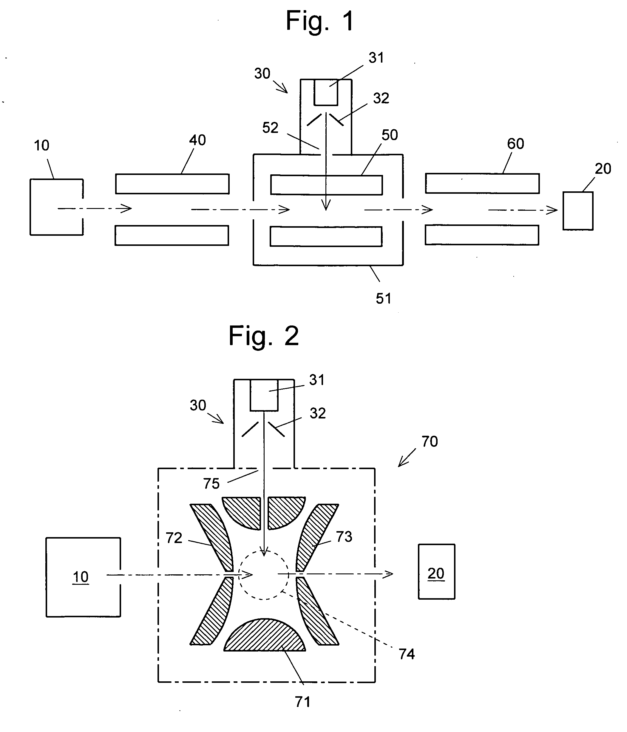
[0044]FIG. 1 schematically shows an example of the construction of the present invention applied to a tandem-in-space mass spectrometer having multiple mass separators connected in series. The mass spectrometer of the present embodiment is an MS / MS mass spectrometer using quadrupole mass filters as the mass separators. It includes an ion source 10, three sets of quadrupole mass filters (the first quadrupole mass filter 40, the second quadrupole mass filter 50, and the third quadrupole mass filter 60) and a detector 20, all of which are located within a vacuum chamber (not shown). The mass spectrometer also has a collision cell 51 enclosing the second quadrupole mass filter 50. The operation of each element is controlled by a controller (not shown) consisting of a central processing unit (CPU) and other devices.

[0045] The collision cell 51 is equipped with a cluster generator 30, which produces a strong cluster beam by performing an adiabatic expansion proce...

second embodiment

[0047] [Second Embodiment]

[0048]FIG. 2 schematically shows an example of the construction of the present invention applied to a tandem-in-time mass spectrometer for capturing, breaking and mass-analyzing the ion with a single mass spectrometer. The tandem-in-time mass spectrometer according to the present invention uses an ion trap as the aforementioned mass separator, including the ion source 10, an ion trap 70, the detector 20 and the cluster generator 30, all of which are located within a vacuum chamber (not shown). The ion trap 70 consists of a ring electrode 71 and a pair of end cap electrodes 72 and 73 facing each other across the ring electrode 71. A radio-frequency high voltage is applied to the ring electrode 71 to create a quadrupole electric field within the space surrounded by the ring electrode 71 and the two end cap electrodes 72 and 73. This space, in which ions are to be captured, is called the ion-capturing space 74 hereinafter. Meanwhile, an auxiliary alternating v...

third embodiment

[0050] [Third Embodiment]

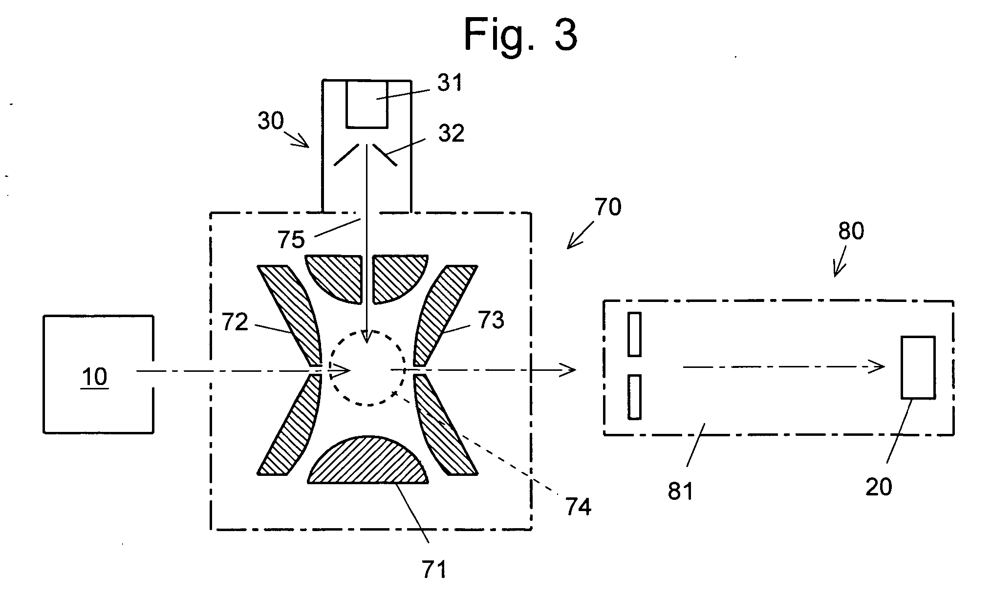
[0051]FIG. 3 schematically shows another example of the construction of the present invention applied to a tandem-in-space mass spectrometer. In the present embodiment, the tandem-in-space mass spectrometer includes the ion trap 70 as the first mass separator and a time-of-flight mass spectrometer (TOFMS) 80 as the second mass separator. The ion source 10, the ion trap 70 and the TOFMS 80 are located within a vacuum chamber (not shown). The ion trap 70 is equipped with the cluster generator 30. These elements are operated by a controller (not shown).

[0052] A sample ion released from the ion source 10 is initially introduced into the ion trap 70, which performs the precursor selection process to trap a desired ion. Meanwhile, the cluster generator 30 supplies clusters into the ion-capturing space 74, where the CID process is performed to break the sample ion into fragment ions, as explained thus far. After an adequately long period of time for the dissociati...


PUM


Abstract

The present invention provides a mass spectrometer capable of breaking even a sample molecule having a large molecular weight by a CID process. In an embodiment of the present invention, the mass spectrometer includes an ionizing source 10 for turning a sample into ions, mass-separating sections 40 and 60 for mass-separating the sample ions, a detecting section 20 for detecting the mass-separated ions, and a collision section (collision cell) 51 located on an ion path extending from the ionizing source 10 through the mass-separating sections 40 and 60 to the detecting section 20. It also includes a cluster generator 30 for producing clusters of atoms or molecules. The clusters produced by the cluster generator 30 are introduced into the collision cell 51. The use of the clusters having a huge mass as the target gas in the CID process enables the collision energy of the sample ions to be efficiently assigned to the breaking of the ions.

Description

[0001] The present invention relates to a mass spectrometer. More specifically, it relates to a mass spectrometer capable of dissociating sample ions having large molecular weight into fragments and performing the mass analyses of those resultant ions. BACKGROUND OF THE INVENTION [0002] One of the known methods for obtaining structural information about the molecular ions by mass spectrometry is an MS / MS analysis (or MSn analysis). In a typical MS / MS analysis, an ion having a desired mass-to-charge ratio is first separated from the material to be analyzed. This ion is called the precursor ion, or the parent ion. Next, the precursor ion thus separated is broken into fragment ions by a collision-induced dissociation (CID) process. Finally, the fragment ions (or daughter ions) produced by the dissociation process, are mass-analyzed to obtain a mass spectrum, which provides information about the molecular structure of the precursor ion. [0003] In the CID process, the sample ion collides...

Claims


Application Information

Patent Timeline
IPC IPC(8): H01J49/00
CPCH01J27/026H01J49/005
Inventor FURUHASHI, OSAMUOGAWA, KIYOSHI
Owner SHIMADZU CORP
Learn More