Method for developing a transmit coil of a magnetic resonance system

a technology of magnetic resonance system and transmit coil, which is applied in the direction of magnetic measurement, instruments, measurement devices, etc., can solve the problems of increasing the complication reducing the quality factor, and the emission efficiency of the antenna unit, so as to reduce the cost of manufacture and maintenance the quality factor and emission efficiency of the rf transmit coil is high, and the effect of reducing the cost of the transmission coil

Inactive Publication Date: 2007-04-19
SIEMENS AG
View PDF1 Cites 13 Cited by
  • Summary
  • Abstract
  • Description
  • Claims
  • Application Information

AI Technical Summary

Benefits of technology

[0022] Adding the series capacitor before the cable can make it possible to decouple before the series capacitor instead of as is originally the case, between antenna units i.e. within the MRI magnetic body, and realize decoupling outside the magnetic body. Since the present invention, by simply using the decoupling capacitor, can decouple the inductive and capacitive couplings of the RF transmit coil simultaneously, it ensures a high quality factor and emission efficiency of the RF transmit coil. Similarly, since the series capacitor compensates the phase shift resulting from the connecting cable to zero, the connecting cables do not have to be limited to half-wavelength, but can be shortened according to the practical situation, thus the energy consumption in the cable will be reduced. Since the decoupling circuit of the RF transmit coil is moved outside the magnetic body, it does not need to install the decoupling elements which require different values based on practical conditions and professionals to adjust between the antenna units, and hence the antenna units can be designed as mutually exchangeable standard parts, so that the cost of the manufacture and maintenance for the RF transmit coil can be reduced.

Problems solved by technology

In the prior art, there are mainly two methods for detuning the RF transmit coil, one is adding detuned circuits within the antenna units, but this method would decrease the quality factor (also called Q factor) and emission efficiency of the antenna units, at the same time also increase the complication of the antenna units, and thus the application range of this method is relatively limited; the other is connecting with detuned circuits outside the RF transmit coil via a cable to realize detuning, however, in this case, the length of the cable is required to be integer multiples of half-wavelength (λ / 2), thus the short-circuit condition of the detuned circuit can be inputted to the antenna units.
This requirement of using the half-wavelength cable brings a very serious drawback to the structure and performance of the RF transit coil: a certain amount of consumption will occur when the current from the resonance circuit consisting of the half-wavelength cable and the circuits inside and outside the antenna unit passes through the cable, and this consumption will decrease the emission efficiency of the antenna units; especially when the operating wavelength of the RF transmit coil is relatively long, or when it is applied to a low field system, the half-wavelength cable will be relatively long, which makes said consumption more significant.
Since couplings tend to occur during the operation among each of the antenna units, these couplings will seriously affect the normal work of the antenna units and the RF transmit coil, and decrease the operating efficiency of the RF transmit coil, especially when the RF transmit coil operates at high power and high voltage, the coupling will be more critical.
In addition, when the antenna units operate at the edge of said bandwidth, the decoupling will deteriorate obviously.
At present there are two methods for solving these problems: one is using different antenna units that operate in different bandwidths and adjusting the centre frequency of said different antenna units respectively, although using this method means that different antenna units need to be used for different bandwidths, and these antenna units cannot be interchangeable, which not only increases the complication of the manufacture and maintenance of the RF transmit coil, but also increases the cost greatly; the other method is using a variable capacitor or inductor connected between the corresponding antenna units to decouple directly, thus achieving decoupling of the whole operating bandwidth.
Since the antenna units of the RF transmit coil operate under high power and high voltage, the decoupling capacitors are required to have high-voltage tolerance, whereas it is hard to make the value of the capacitors very high, and it is also very expensive; if inductors are used for the decoupling, huge-volume inductors are needed to meet the requirements; in practical application, several variable capacitors or inductors are often needed to meet the decoupling requirements, which increases the cost greatly.
Moreover, the inner space of the MRI system is very limited and valuable, but said decoupling capacitors or inductors are fitted between the antenna units, and their huge volume occupies a mass of magnetic space.
It is very inconvenient to adjust or replace the decoupling capacitor or inductor in the magnetic limited inner space and intense magnetic field, and the operation of the adjustment and replacement is very complicated which needs professionals and technical equipment.
This decoupling method for the RF transmit coil in the prior art has the following drawbacks: the decoupling capacitors or inductors are connected directly between the corresponding antenna units, that is, the decoupling is within the magnetic body, therefore, the antenna units cannot be made into standard parts, which need to use different values of the decoupling capacitors or inductors according to different operating frequencies, and need to adjust said decoupling capacitors or inductors within the magnetic limited space during installation.
Moreover, in the case of the inductive coupling occurring between the antenna units 1 to 4, in the prior art the solution is to connect the decoupling inductors between the corresponding antenna units to compensate, but compared with the decoupling capacitors, the quality factor of the decoupling inductors is smaller than that of the decoupling capacitors and consumption tends to occur, and the volume of decoupling inductors is much larger, which needs more valuable magnetic limited space.

Method used


Image

  • Method for developing a transmit coil of a magnetic resonance system
  • Method for developing a transmit coil of a magnetic resonance system
  • Method for developing a transmit coil of a magnetic resonance system

Examples


Embodiment Construction

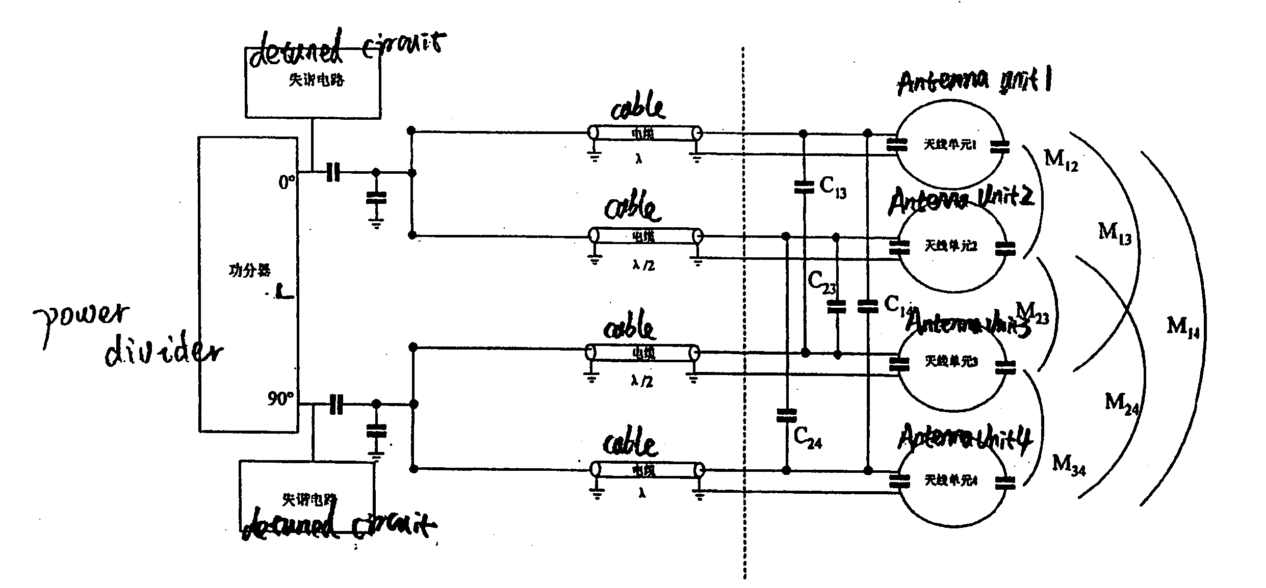
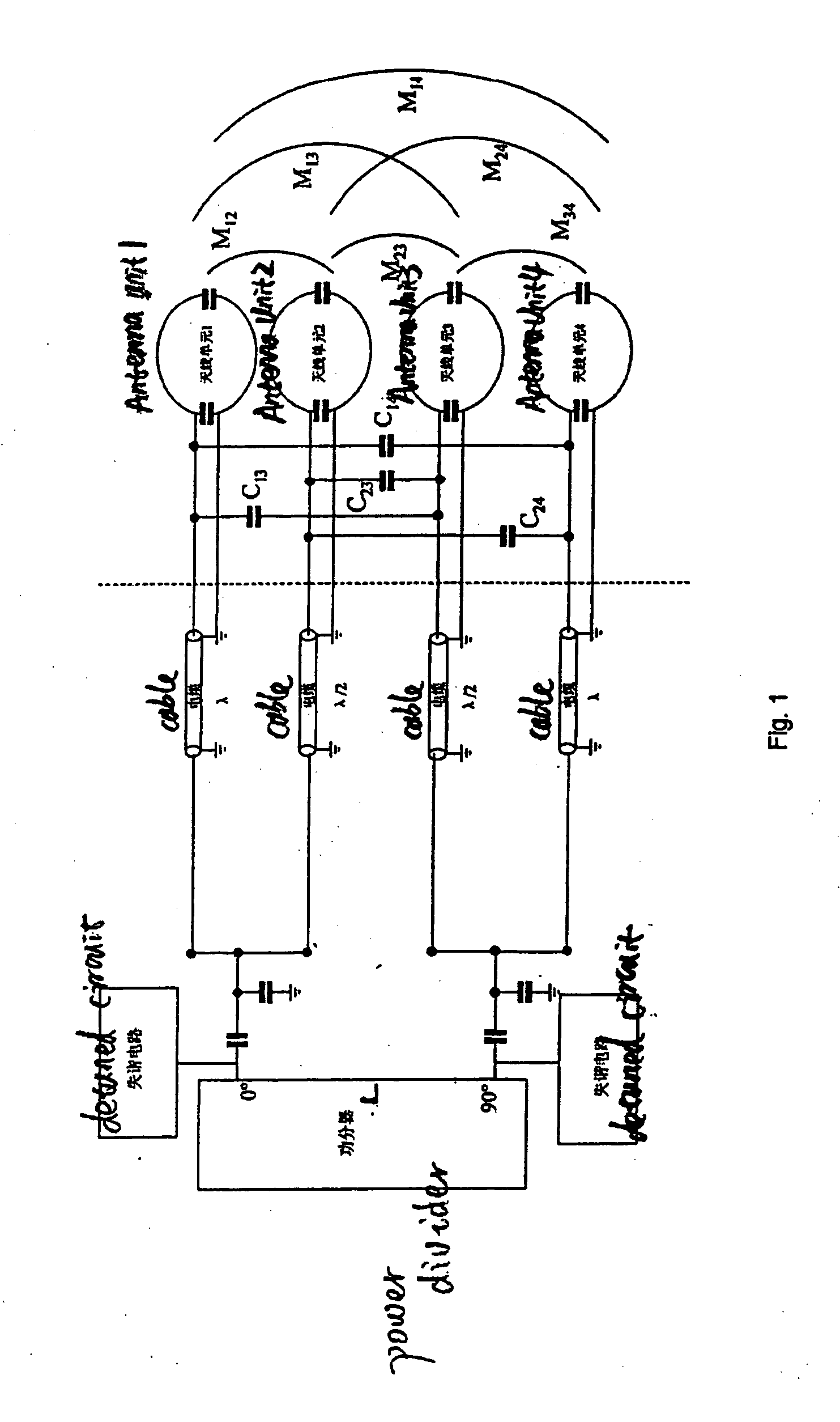
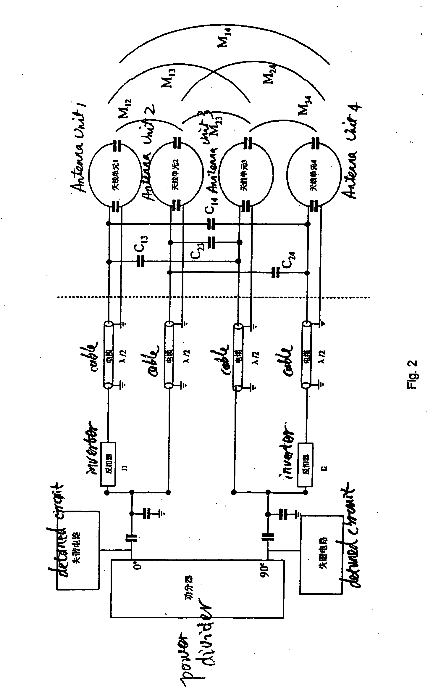
[0029] Referring to FIG. 2, the section of stimulus signals input and detuned circuit outside an RF transmit coil in the prior art is shown to the left of the broken line, and the section of the RF transmit coil and decoupling parts of the RF transmit coil in the prior art is shown to the right of the broken line. In this embodiment, it is taken as an example that the RF transmit coil has four antenna units i.e. antenna units 1 to 4 as shown in FIG. 2. The detuned circuit and the orthogonal stimulus signals are respectively connected with the antenna units 1 to 4 via a half-wavelength cable. Within this, a 0° signal and 90° signal are divided from a power divider, and the 0° signal passes through a half-wavelength cable directly and passes through an inverter I1 first and then a half-wavelength cable respectively to carry 0° and 180° signals into the antenna units; the 90° signal passes through a half-wavelength cable directly and passes through an inverter 12 first and then a half-...


PUM


Abstract

In a method for decoupling an RF transmit coil in a magnetic resonance imaging system, the RF transmit coil has more than one antenna unit and stimulus signals are inputted to said antenna units via connecting cables. A capacitor is connected in series before each of the cables and the value of the series capacitor is such that it just compensates the signal phase shift caused by the connecting cable to zero. Decoupling circuits are connected between said antenna units and before the series capacitors for decoupling said antenna units. The decoupling circuit, by simply employing the decoupling capacitor, decouples the inductive coupling and capacitive coupling between the antenna units simultaneously. The method can be employed to decouple an RF transmit coil outside a magnetic body via the use of a decoupling capacitor.

Description

BACKGROUND OF THE INVENTION [0001] 1. Field of the Invention [0002] The present invention relates to a method for decoupling an antenna array of an RF transmit coil, and more particularly, to a method for decoupling an RF transmit coil which decouples an antenna array of an RF transmit coil in a Magnetic Resonance Imaging (MRI) system, outside the RF transmit coil. [0003] 2. Description of the Prior Art [0004] An RF transmit coil is an important part of a Magnetic Resonance Imaging (MRI) system, which is used for producing variable pulse sequences so as to stimulate the hydrogen atomic nucleus in a human body to generate magnetic resonance signals. [0005] The RF transmit coil includes an antenna array, and the antenna array includes several antenna units which are fitted in the magnetic body of the MRI system. [0006] In the prior art, there are mainly two methods for detuning the RF transmit coil, one is adding detuned circuits within the antenna units, but this method would decreas...

Claims


Application Information

Patent Timeline
Patent Type & Authority Applications(United States)
IPC IPC(8): G01V3/00
CPCG01R33/3415G01R33/3628
Inventor DU, JIAN JUNWANG, JIAN MIN
Owner SIEMENS AG
Why Eureka
Try Eureka