
Method of forming directional wireless networks using in-band channels

Active Publication Date: 2007-04-19
THE BOEING CO
View PDF15 Cites 40 Cited by
  • Summary
  • Abstract
  • Description
  • Claims
  • Application Information

AI Technical Summary

Benefits of technology

[0015] A further advantage of the present invention is that it provides a bounded discovery time for nodes that are relatively distant.
[0016] Another advantage of the present invention is that nodes are more likely to discover the nearest neighbor first.
[0017] Yet another advantage of the present invention is that the highest antenna gains can be used by both transmitters and receivers to discover neighbors at great distances.

Problems solved by technology

The MANET network lacks any central server to support standard networking functions such as routing, security, neighbor discovery and data forwarding.
Announcement packets that are broadcast using an omni-directional transmission source are susceptible to detection or interception by enemy receivers or other unintended recipients.
This is problematic since they must be high enough in power to discover neighbors at the maximum network formation range.
Furthermore, omni-directional receivers for receiving the AP signals may be easily jammed by enemy transmitters.
PAAs can be redirected in a few microseconds, which is a characteristic that cannot be achieved with mechanically-steered antennas.
Heretofore, directional antennas have been unsuitable for MANET, because directional antenna communications require the transmitting and receiving nodes to be aligned.
Even if two nodes are within range, they cannot discover each other if their respective antennas are not aligned.
In that case, an additional antenna must be provided at the node, dedicated solely to the ND process, and adding additional cost and weight to the node.

Method used


Image

  • Method of forming directional wireless networks using in-band channels
  • Method of forming directional wireless networks using in-band channels
  • Method of forming directional wireless networks using in-band channels

Examples


Embodiment Construction

[0027] The present invention provides a method of forming a mobile network using directional antennas. Directional antennas, such as Phased Array Antennas (PAA) can focus radiation energy in a narrow angle to form wireless links between nodes in a network. Directional antennas have a number of advantageous properties for communications networking—high data transmission rates, long range communication, as well as LPD, LPE, LPI and AJ as mentioned above. The present invention implements neighbor discovery with blind announcements without sacrificing the inherent LPD advantages of directional antennas.

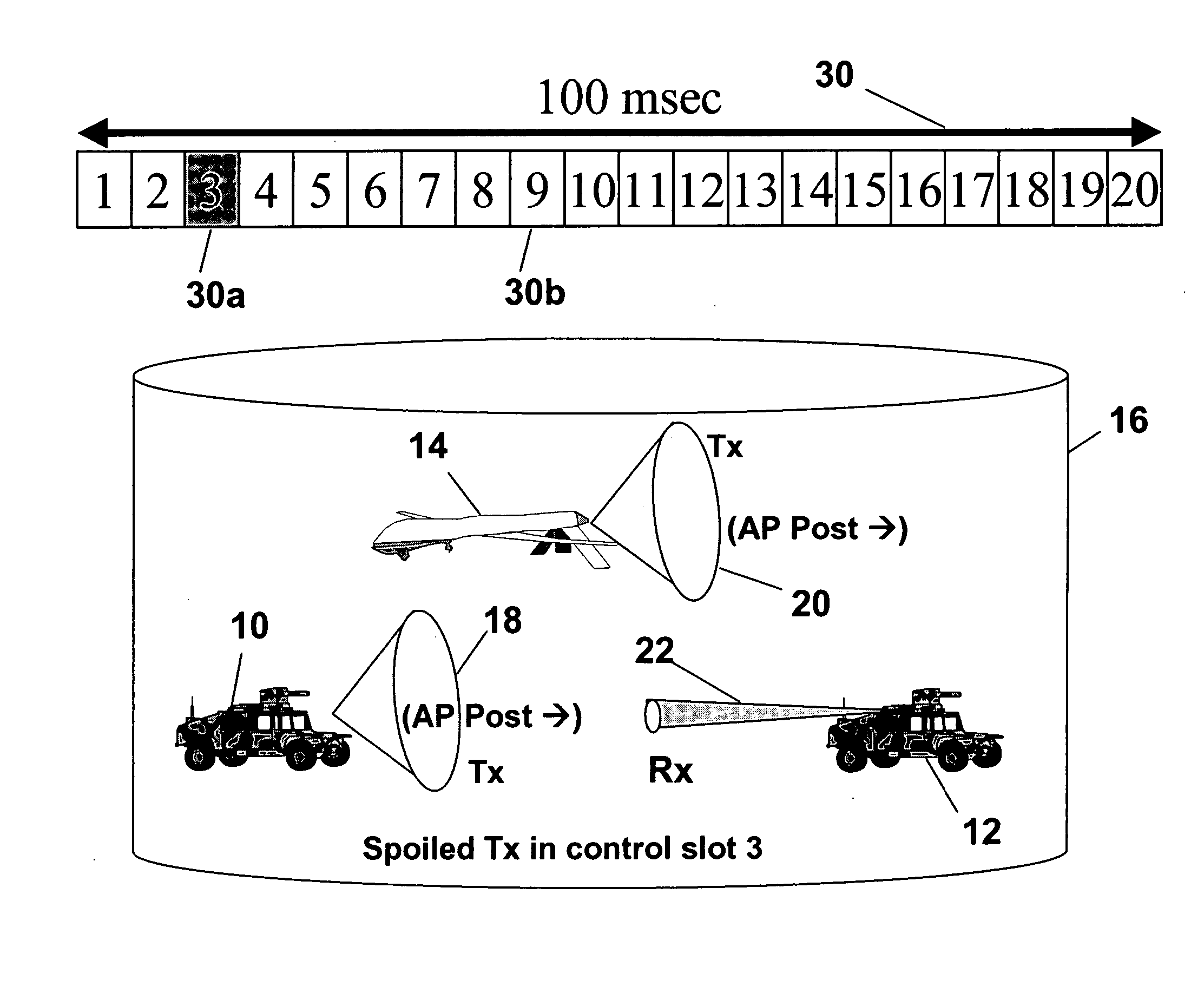
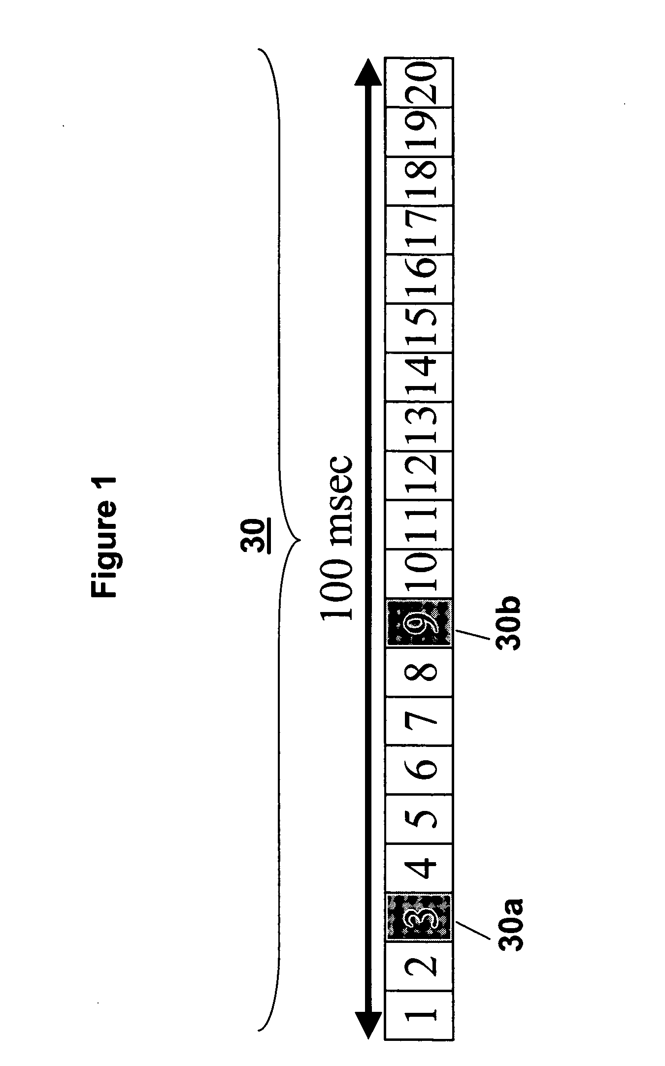
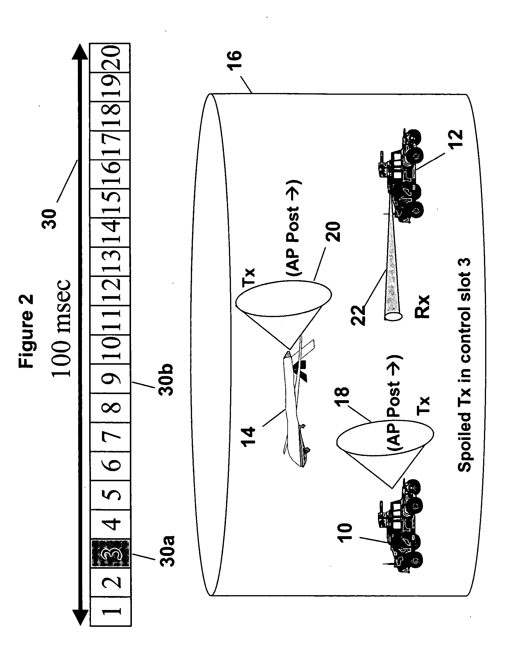
[0028] The neighbor discovery process, i.e., the sending and receiving of the announcement packets (AP), exchanging position information and selecting slots for a persistent link, is based on Spatial-Time Division Multiple Access (S-TDMA) protocol architecture. Referring to FIG. 1, the neighbor discovery process of the present invention uses a control structure or architecture generally ...


PUM


Abstract

The present invention is directed to a method of forming a mobile network using Phased Array Antennas. Mobile nodes search for nodes with which to form a network by either transmitting low level announcement signals on a wide spoiled beam directional antenna at progressively increasing power levels, or by receiving announcement signals using a high-gain, narrow directional beam. Low power announcements are compensated for by processing gain in the receive modem. Nodes randomly decide at each step of the scan whether to transmit or receive. Two control slots in an epoch are used for neighbor discovery. The first control slot is to announce or receive an announcement, and the second control slot is used to acknowledge the receipt of an announcement packet. The neighbor discovery process uses in-band communications. The directional communications permit simultaneous links in close proximity to other links without interference.

Description

FIELD OF THE INVENTION [0001] The present invention is directed to mobile communications networks, and more particularly to a method of forming mobile ad hoc wireless networks using directional antennas. BACKGROUND OF THE INVENTION [0002] Mobile ad hoc networking technology (MANET) describes a self-organized, self-healing wireless interconnection of communications devices to form an independent communications network, or a network extension of a wired networking infrastructure. The most important characteristic that distinguishes MANET is the absence of a fixed infrastructure. The MANET network lacks any central server to support standard networking functions such as routing, security, neighbor discovery and data forwarding. [0003] MANET has application to military communications networks. Security is of paramount concern in military applications. Low probability of detection (LPD), low probability of interception (LPI), low probability of enemy exploitation (LPE) and anti-jamming c...

Claims


Application Information

Patent Timeline
IPC IPC(8): H04Q7/20H04W16/28
CPCH04W16/28Y02D30/70
Inventor NORRIS, PAUL R.NAST, DOUGLAS P.PEI, GUANGYUKIM, JAE H.
Owner THE BOEING CO
Learn More