
Apparatus and method for thermal ablation of uterine fibroids

Inactive Publication Date: 2007-04-19
GALIL MEDICAL
View PDF85 Cites 111 Cited by
  • Summary
  • Abstract
  • Description
  • Claims
  • Application Information

AI Technical Summary

Benefits of technology

[0024] According to further features in preferred embodiments of the invention described below, the system further comprises a treatment probe lumen sized to accommodate the at least one treatment probe, the lumen being switchable between an open state permitting a treatment probe to enter and exit the treatment probe lumen and a closed state which prevents treatment probes from entering and from exiting the treatment probe lumen. Preferably the open state is characterized by a first configuration wherein the opening is aligned with the treatment probe lumen, enabling translation of a treatment probe into and out of the lumen, and the closed state is characterized by a second configuration wherein the opening is unaligned with the treatment probe lumen and translation of a treatment probe into and out of the treatment probe lumen is prevented. Transition from the open state to the closed state may be effected by rotating a cover of the delivery sleeve with respect to a body of the delivery sleeve.
[0076] The present invention further successfully addresses the shortcomings of the presently known configurations by providing an apparatus and method enabling cryoablation within the uterus while protecting tissues of the cervix from damage by cold.

Problems solved by technology

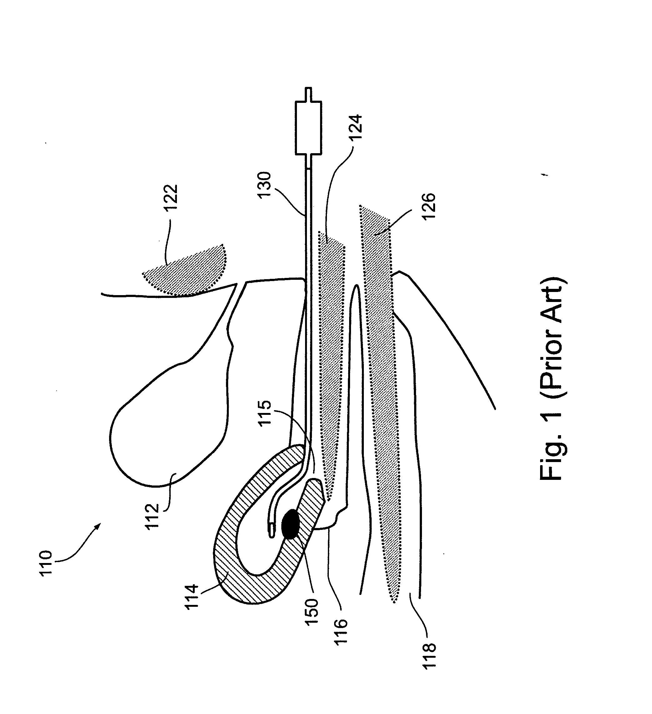
Endoscopic cryoablation is currently limited to treating fibroid growth on outer walls of the uterus.
However, often, when a large part of a fibroid is contained within the muscular walls rather than simply projecting into the uterus, repeated treatments are required.
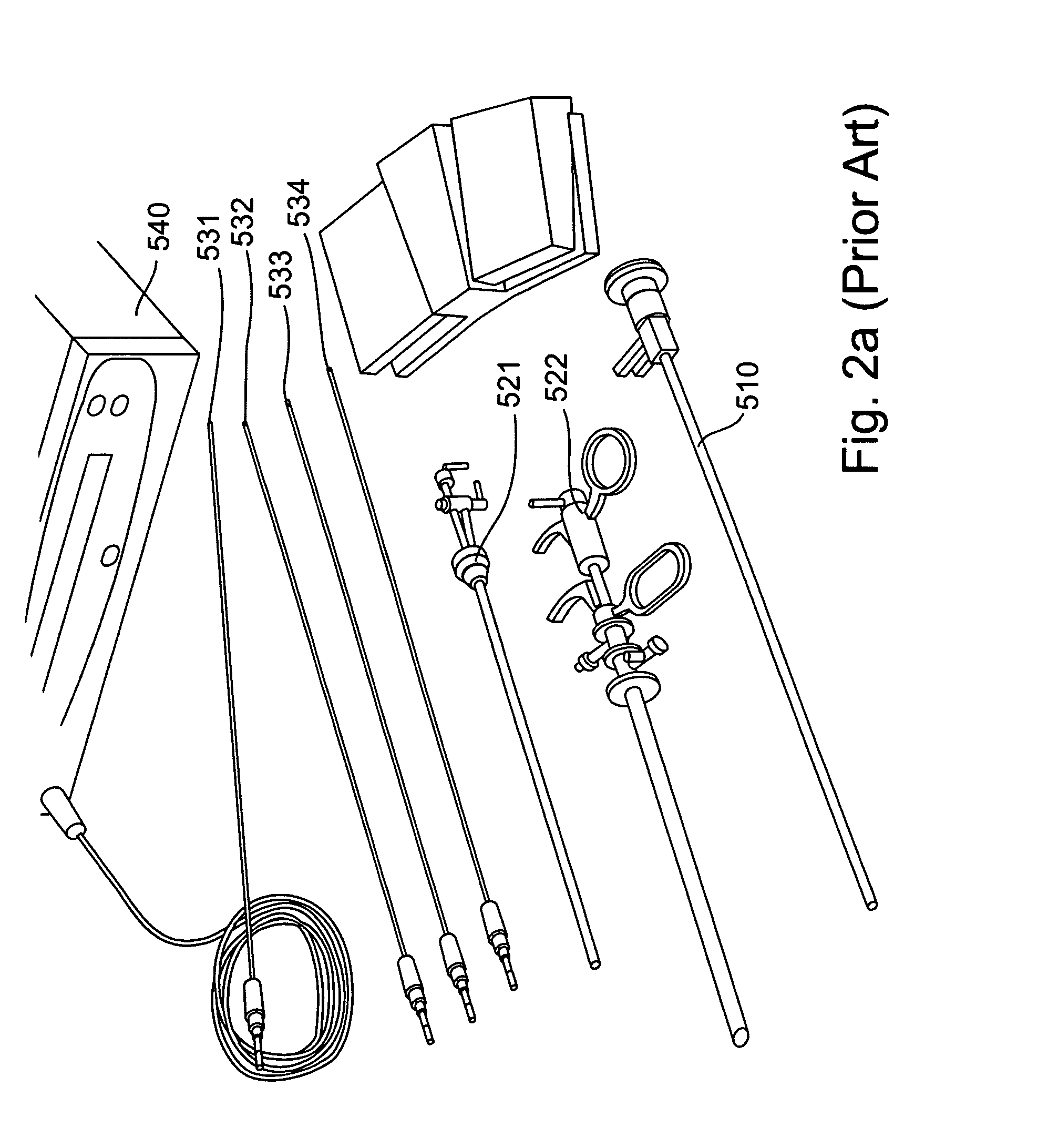
The disclosed system does not provide visual inspection of the treated location and discloses only straight, rigid treating needles.
The maximum practical diameter of hysteroscopes is limited by the size of the cervix opening.
The hysteroscopes known to prior art, the maximum size of working channels provided by hysteroscopes (“working channels” being channels enabling introduction of tools additional to the optical components of the hysteroscope into a treatment area) is consequently also limited.
Uterine surgery, however, provides unique access limitations, in consequence of which hysteroscopes and resectoscopes currently in use for uterine treatment enable only one thermal ablation probe to be delivered to a treatment target such as a fibroid.
However, some fibroids are larger than the maximum size of the ice ball which may be produced by a small-diameter cryoprobe.
It is an additional limitation of currently known technologies, wherein a working channel of a therapeutic hysteroscope is used to introduce a thermal probe into a treatment target, that external connections to the thermal probe and internal dimensions of the working channel are such that probe and hysteroscope are necessarily paired one within the other for the duration of the treatment phase of the thermal operation, thereby preventing use of such a therapeutic hysteroscope with more than one such treatment probe at a time.
It is an additional limitation of currently known technologies that the form of working channels of known hysteroscopes and the form of known thermal treatment probes used therein limit the maneuverability of those probes in the uterine context.
It is a further limitation of known technologies that cold induced by the shafts and cryogen input and exhaust lines of croprobes used for intrauterine cryoablation tends to endanger tissues of the cervix.

Method used


Image

  • Apparatus and method for thermal ablation of uterine fibroids
  • Apparatus and method for thermal ablation of uterine fibroids
  • Apparatus and method for thermal ablation of uterine fibroids

Examples


Embodiment Construction

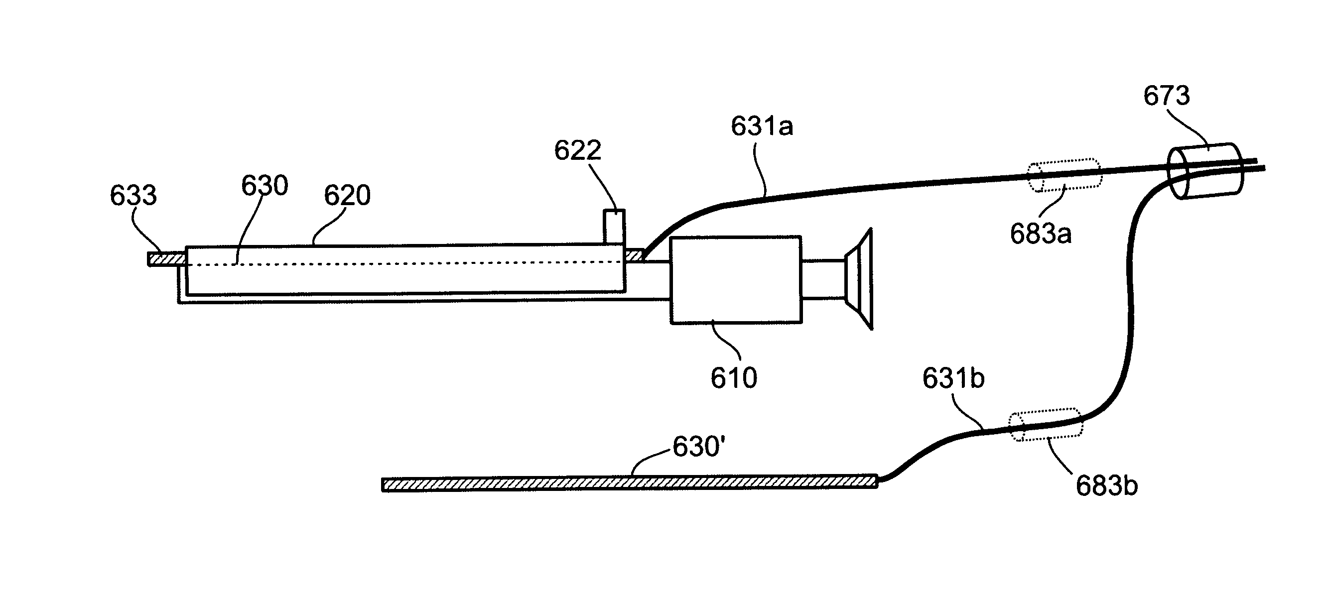
[0104] The present invention is of apparatus and methods for delivering thermal treatment probes to a treatment target within a body cavity, and in particular to delivery of a plurality of cryoprobes to a fibroid within a uterus, thereby enabling thermal ablation of the fibroid. Specifically, the present invention enables to deliver a plurality of thermal treatment probes through the cervix into the uterus, and there to deploy those probes in a dispersed configuration appropriate for thermal treatment of a large fibroid.

[0105] Before explaining at least one embodiment of the invention in detail, it is to be understood that the invention is not limited in its application to the details of construction and the arrangement of the components set forth in the following description or illustrated in the drawings. The invention is capable of other embodiments or of being practiced or carried out in various ways. Also, it is to be understood that the phraseology and terminology employed he...


PUM


Abstract

The present invention relates to apparatus and methods for thermally ablating uterine fibroids. More particularly, the present invention relates to a conduit having a plurality of channels for delivering a plurality of thermal ablation probes to an organic target such as a uterine fibroid, the probes being delivered in such configuration and orientation as to enable efficient and thorough ablation of the fibroid. In a preferred embodiment, the conduit is formed as a sleeve having a large central lumen sized to accommodate a hysteroscope, channels sized to accommodate cryoprobes are used as thermal ablation probes, and comprises thermal insulation materials serving to protect the cervix from damage by cold. The present invention further relates to bent cryoprobes usable in conjunction with such a conduit and designed to exit therefrom in a desired configuration useful for ablating a large fibroid.

Description

RELATED APPLICATIONS [0001] This Application is a continuation-in-part of pending U.S. patent application Ser. No. 11 / 055,597 filed Feb. 11, 2005, which is a continuation of U.S. patent application Ser. No. 09 / 987,689 filed Nov. 15, 2001, now abandoned, which is a continuation-in-part of U.S. patent application Ser. No. 09 / 860,486 filed May 21, 2001, now U.S. Pat. No. 6,706,037 issued Mar. 16, 2004, which claims the benefit of U.S. Provisional Patent Application No. 60 / 242,455, filed Oct. 24, 2000. [0002] This Application is also a continuation-in-part of pending U.S. patent application Ser. No. 11 / 185,699 filed Jul. 21, 2005, which is a divisional of U.S. patent application Ser. No. 10 / 151,310 filed May 21, 2002, now abandoned, which claims the benefit of U.S. Provisional Patent Application No. 60 / 300,097 filed Jun. 25, 2001 and U.S. Provisional Patent Application No. 60 / 291,990 filed May 21, 2001. [0003] This Application also claims the benefit of U.S. Provisional Patent Applicati...

Claims


Application Information

Patent Timeline
IPC IPC(8): A61B18/18A61B17/20
CPCA61B2017/3447A61B2017/4216A61B2018/00101A61B2018/0262A61B2018/1495A61B2019/4063A61B1/00073A61B1/00098A61B1/00135A61B1/00154A61B1/018A61B1/303A61B17/3421A61B17/42A61B18/02A61B2017/3445A61B2090/0463
Inventor BLIWEIS, MORDECHAIBERZAK, NIRLIVNEH, SHIMONHEFETZ, YARONTAL, YARONZVULONI, RONI
Owner GALIL MEDICAL
Learn More