
Systems and methods for controlling foaming

a technology of foaming and foam control, applied in the field of systems and methods of controlling foaming, can solve the problems of toxicity level in food products, affecting the quality of food products, so as to achieve the effect of controlling or reducing foam, reducing toxicity, and reducing toxicity

Inactive Publication Date: 2007-04-26
HOROS TECH
View PDF6 Cites 20 Cited by
  • Summary
  • Abstract
  • Description
  • Claims
  • Application Information

AI Technical Summary

Benefits of technology

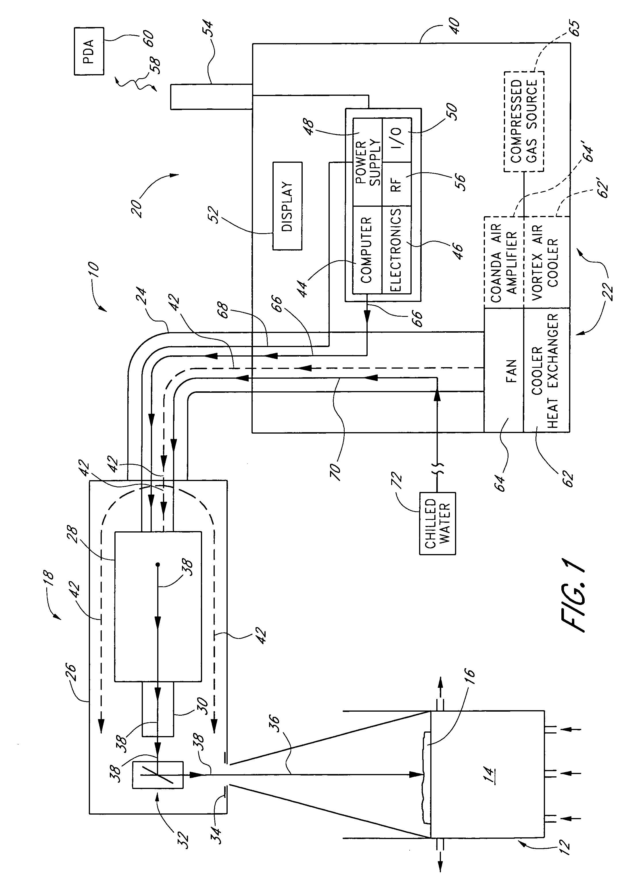
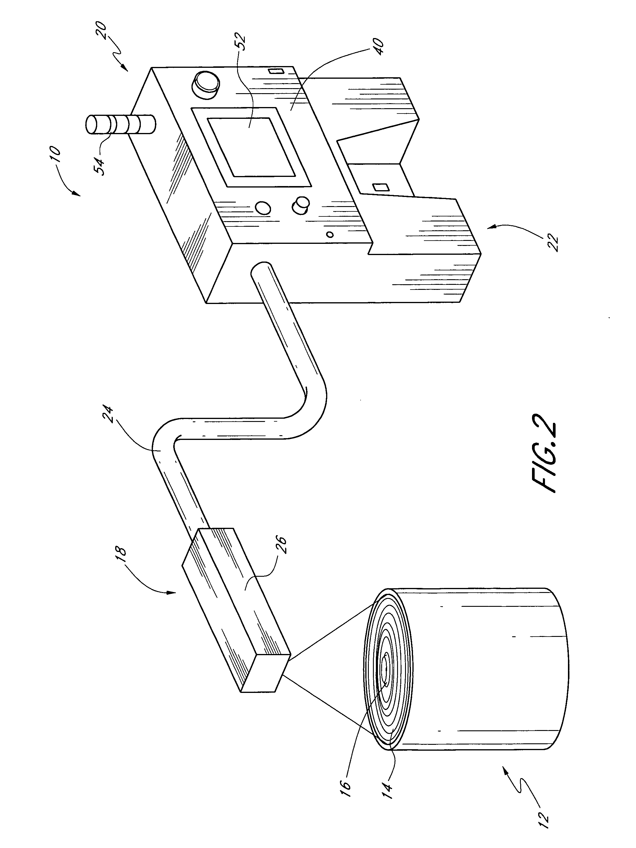
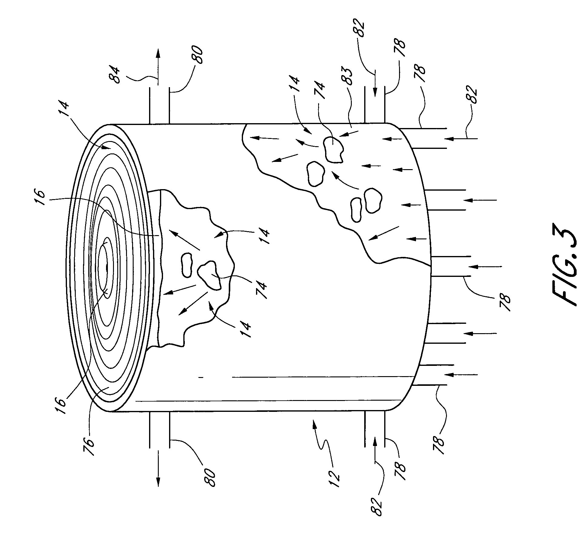
[0008] Some embodiments provide a foam controlling system that uses electromagnetic energy to cut foam on the surface of a solution or liquid in a processing tank into at least two portions prior to the foam propagating and reaching the perimeter of the tank such that currents within the solution or liquid dissipate at least one of the foam portions. Some embodiments provide a purging fluid to a laser head unit of the foam controlling system to reduce the dew point therein and thereby reduce or substantially eliminate undesirable condensation that could otherwise cause adverse optics contamination. Advantageously, the versatility and simplicity of the foam controlling system as well as its adaptability to various manufacturing formats makes the system an economical full plant solution.
[0011] Yet another embodiment provides an apparatus for controlling foaming in a tank containing a liquid which generates foam. The apparatus generally comprises a housing, a source of electromagnetic radiation and a source of purging fluid. The source of electromagnetic radiation produces an electromagnetic beam. The beam propagates along a beam path through at least a portion of the housing and towards the foam. The source of purging fluid provides the purging fluid to the housing such that dew point along a portion of the beam path within the housing is reduced.
[0014] Advantageously, the systems and methods of controlling foaming in accordance with certain embodiments of the invention can be easily tailored or customized to larger scale formats without environment impact to manufacturing plant personnel. Another advantage is that certain embodiments of the systems and methods of controlling foaming are effective in controlling or reducing foam over large areas.
[0015] Some embodiments utilize a carbon dioxide (CO2) laser as an electromagnetic energy source to cut foam and control it. One advantage that justifies the use of the CO2 laser is its cost effectiveness in power-per-dollar and reliability. Industrial CO2 lasers have advantageously been proven in the field to last up to 5 years or more without being recharged, even while running continuously. The CO2 laser of certain embodiments of the invention is advantageously a readily available laser configured for industrial applications. The CO2 laser desirably provides an economical solution for a majority of applications.
[0016] Certain embodiments of the system for controlling foaming can be readily tailored or customized to two-axis geometrical configurations with simple software modifications. Many different coordinate systems can be programmed into the software, as required or desired. Advantageously, replica units can be used in many manufacturing areas creating a full plant solution with a single system design. This desirably allows common spare parts to be shared throughout a manufacturing plant.

Problems solved by technology

One conventional approach utilizes chemical additives for this purpose which can have several undesirable consequences.
For example, in the food processing industry, such chemical additives can contaminate, pollute, taint or even cause some level of toxicity in the food product.
Undesirable foam can lead to inefficient mixing, poor productivity, reduced vessel capacity, and equipment failure in many common industrial processes.
Such foams can fool sensor devices that monitor liquid levels in critical processes.
Some foams can overwhelm a processing plant, disadvantageously shutting down manufacturing.
In wastewater treatment, foams build up and entrap bio-organisms that produce foul odors as well as have the potential to overflow causing undesirable production disruption.
Another conventional approach to the control of foam build up is a sonic technology which disadvantageously has inherent environmental issues where plant personnel are in close proximity to the emitting device.
Yet another conventional approach is a mechanical technology which has limited adaptability and versatility, in particular, as a whole plant solution.

Method used


Image

  • Systems and methods for controlling foaming
  • Systems and methods for controlling foaming
  • Systems and methods for controlling foaming

Examples


Embodiment Construction

[0042] The preferred embodiments of the invention described herein relate generally to systems and methods of controlling foaming in aqueous and non-aqueous solutions and, in particular, to controlling foaming by a laser and a scanning distributing apparatus which cuts foam into at least two portions so that at least one portion is dissipated and / or collapsed, and reducing dew point along at least a portion of a beam path of the laser to advantageously provide for substantially optimal performance and substantially eliminate optic contamination.

[0043] While the description sets forth various embodiment specific details, it will be appreciated that the description is illustrative only and should not be construed in any way as limiting the invention. Furthermore, various applications of the invention, and modifications thereto, which may occur to those who are skilled in the art, are also encompassed by the general concepts described herein.

[0044] Some embodiments of the system for ...


PUM

PropertyMeasurementUnit
Temperatureaaaaaaaaaa

Abstract

A foam controlling system uses electromagnetic energy to cut foam on the surface of a solution or liquid in a processing tank into at least two portions prior to the foam propagating and reaching the perimeter of the tank such that currents within the solution or liquid dissipate at least one of the foam portions. A purging fluid is provided to a laser head unit of the foam controlling system to reduce the dew point therein and thereby reduce or substantially eliminate undesirable condensation that could otherwise cause adverse optics contamination. Advantageously, the versatility and simplicity of the foam controlling system as well as its adaptability to various manufacturing formats makes the system an economical full plant solution.

Description

CROSS REFERENCE TO RELATED APPLICATION(S) [0001] This application claims the benefit of U.S. Provisional Application Ser. No. 60 / 729,002, filed Oct. 20, 2005, entitled SYSTEMS AND METHODS FOR CONTROLLING FOAMING, the entirety of which is hereby incorporated by reference herein.BACKGROUND OF THE INVENTION [0002] 1. Field of the Invention [0003] The invention relates generally to systems and methods of controlling foaming in aqueous and non-aqueous solutions. [0004] 2. Description of the Related Art [0005] Foam control or reduction in many aqueous or non-aqueous solution based applications and industrial processes is critical for obtaining optimal performance and high process efficiency. One conventional approach utilizes chemical additives for this purpose which can have several undesirable consequences. For example, in the food processing industry, such chemical additives can contaminate, pollute, taint or even cause some level of toxicity in the food product. [0006] Undesirable foa...

Claims


Application Information

Patent Timeline
IPC IPC(8): B01D19/00A23N15/00C09K3/00
CPCB01D19/02
Inventor CULLEN, ROBERT R.SWEENEY, RICHARD J.
Owner HOROS TECH
Learn More