Construction machine

a construction machine and construction technology, applied in the direction of machines/engines, electric generator control, transportation and packaging, etc., can solve the problems of increased cost, increased construction cost, and increased construction cost, so as to maintain the performance of the inverter/converter, cost and spa

Inactive Publication Date: 2007-04-26
KOBELCO CONSTR MASCH CO LTD
View PDF7 Cites 20 Cited by
  • Summary
  • Abstract
  • Description
  • Claims
  • Application Information

AI Technical Summary

Benefits of technology

[0043] That is, despite the inverter / converter is installed in the engine room, there is obtained a cooling effect sufficient to maintain the performance of the inverter / converter even in the summer season. Besides, there accrues an advantage in point of both cost and space.

Problems solved by technology

Thus, in the conventional hybrid excavator, the dedicated partition wall and the surrounding space are wasteful and this wasteful space narrows an effective volume of the unit mounting space which is originally narrow, making the layout of unit more difficult.
In this case, however, a temperature is apt to rise with hot air present in the engine room 13, with a consequent likelihood of malfunction.
Therefore, a body cooling effect is not sufficient and an increase in temperature of the body to a high level is unavoidable particularly in the summer season.
On the other hand, according to the latter technique which utilizes cold air present within the cabin, it is necessary that a hole for passage therethrough of the duct be formed in each of the cabin 10 and the partition wall 12, so that not only machining is troublesome and the cost rises, but also the space of the engine room is diminished by the duct piping space for example, with a consequent fear of obstructing the layout of other unit.

Method used


Image

  • Construction machine
  • Construction machine
  • Construction machine

Examples


Embodiment Construction

[0052] Embodiments of the present invention will be described hereinunder with reference to FIGS. 1 to 6.

[0053] In the following embodiments, the same portions as in FIGS. 7 and 8 will be identified by the same reference numerals as in those figures and tautological explanations thereof will be omitted.

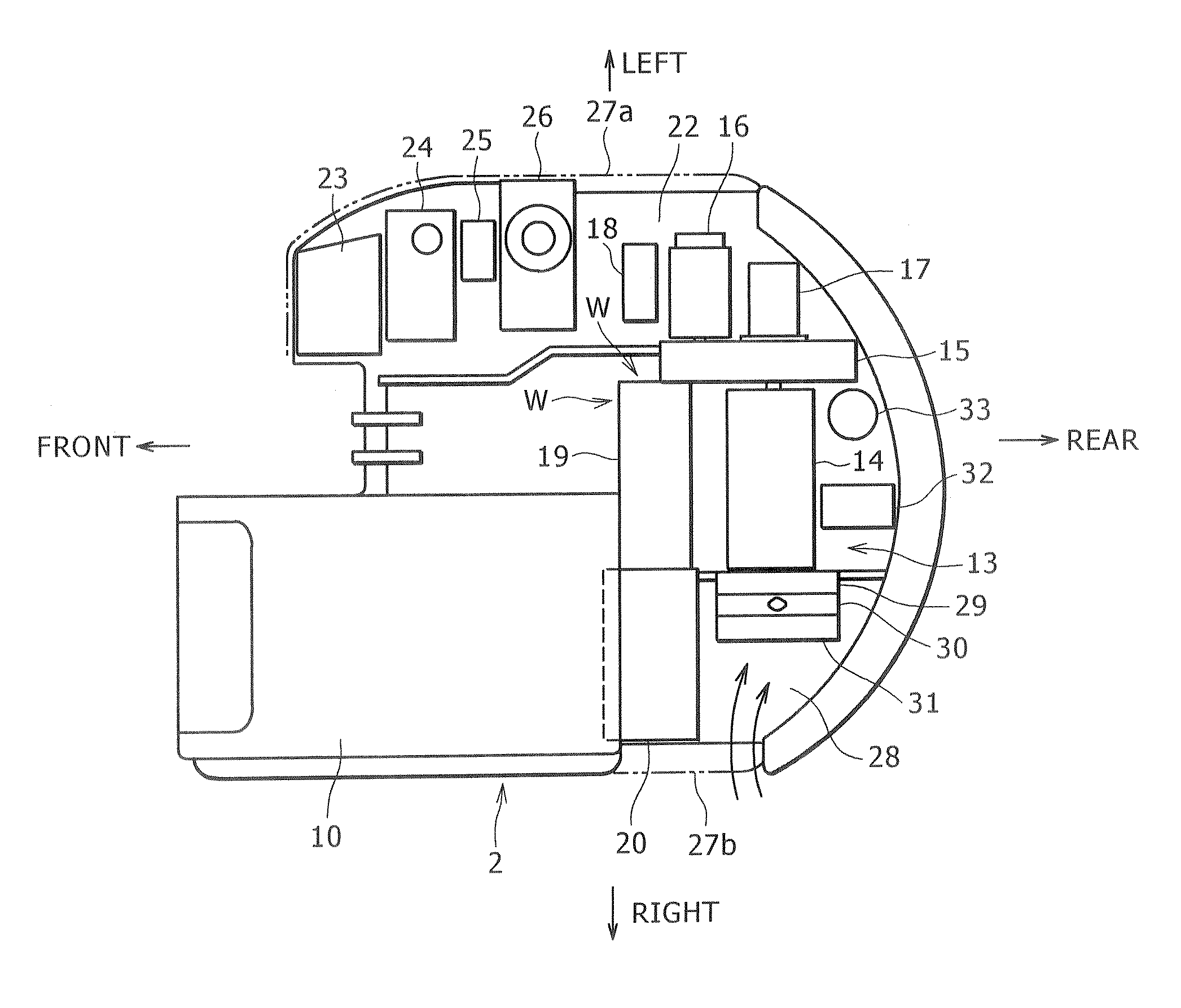
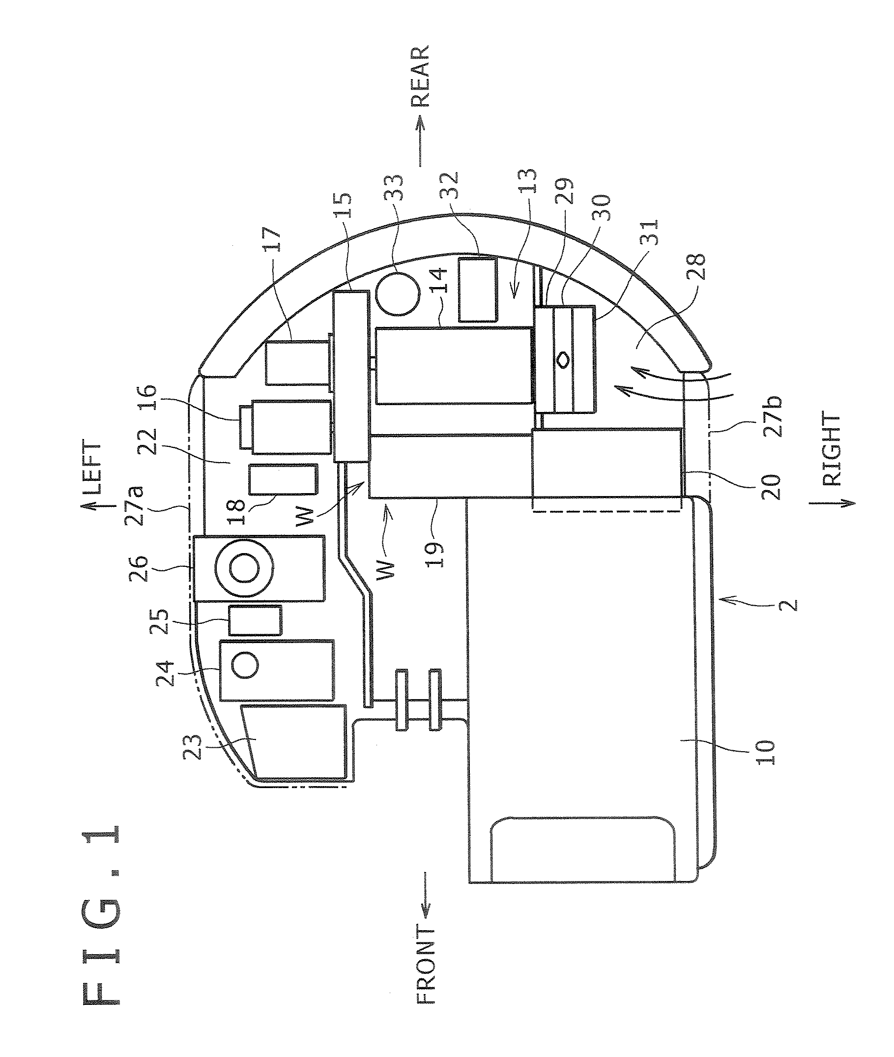
[0054]FIG. 1 is a top view of a layout of unit in an upper rotating body 2.

[0055] An engine 14 is installed in a rear portion of the upper rotating body 2. In front of the engine 14 and behind a cabin 10 there are disposed side by side an electric power storage device 20 on the left side (left side as seen from an operator side sitting on a seat within the cabin 10; this is also true of the directionality of right, left and front, rear which will be referred to below) and an inverter / converter 19 on the right side with little gap between the two.

[0056] On the right side of the engine 14 is disposed a power divider 15 for distributing engine power to both a hydraulic pump 16 and a ...


PUM


Abstract

An inverter/converter as a kind of hybrid unit is composed of a body and a casing covering the body and is disposed in an engine room. An air intake port and an air discharge port each provided with a fan are formed in the casing to configure an internal air cooling device for introducing air present outside the engine room into the casing, allowing the air to flow through the interior of the casing and then discharging it from the air discharge port. A power divider for distributing engine power to a hydraulic pump and a generator-motor is disposed on one of right and left sides of an engine in a rear portion of an upper rotating body. Further, an electric power storage device and the inverter/converter are disposed right and left in parallel behind a cabin and in front of the engine, and a partition wall which defines the engine room is configured by casings of the electric power storage device, the inverter/converter and the power divider.

Description

BACKGROUND OF THE INVENTION [0001] 1. Field of the Invention [0002] The present invention relates to a construction machine using both engine power and electric power. [0003] 2. Description of the Related Art [0004] An excavator shown in FIG. 7 is configured such that an upper rotating body 2 is mounted on a crawler type lower traveling body 1 so as to be rotatable about an axis of ordinate and an excavating apparatus 9 equipped with a boom cylinder 6, an arm cylinder 7 and a bucket cylinder 8 for actuating a boom 3, an arm 4 and a bucket 5 respectively is attached to a front portion of the upper rotating body 2. [0005] A cabin 10 is mounted on a front left side of the upper rotating body 2 and a counterweight 11 is mounted on a rear end portion of the upper rotating body 2. [0006] Behind the cabin 10 is mounted a partition wall 12 in a transverse direction. An engine room 13 is formed between the partition wall 12 and the counterweight 11 and an engine 14 as a power source is insta...

Claims


Application Information

Patent Timeline
Patent Type & Authority Applications(United States)
IPC IPC(8): H02P9/04B60K6/26B60K6/28B60K6/365B60K6/40B60K6/485B60L50/16E02F9/08E02F9/20
CPCE02F9/0866E02F9/2075
Inventor KOMIYAMA, MASAYUKIMANABE, TETSUNORIMINO, AKIHITO
Owner KOBELCO CONSTR MASCH CO LTD
Why Eureka
Try Eureka