

Optical scanning system and image forming apparatus using the same
an optical scanning system and image forming technology, applied in the direction of inking apparatus, instruments, lenses, etc., can solve the problems of deteriorating resolving power or broadening of fine lines, adversely affecting the image drawn on the scanned surface, and affecting the spherical aberration to be produced by the input optical system. , to achieve the effect of reducing the spherical aberration to be produced by the input optical system, good light spot, and high precision
- Summary
- Abstract
- Description
- Claims
- Application Information
AI Technical Summary
Benefits of technology
Problems solved by technology
Method used
Image

Examples
embodiment 1
[Embodiment 1]
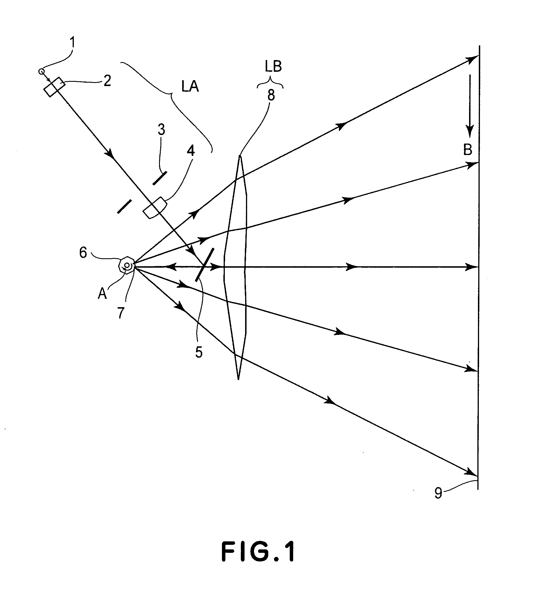
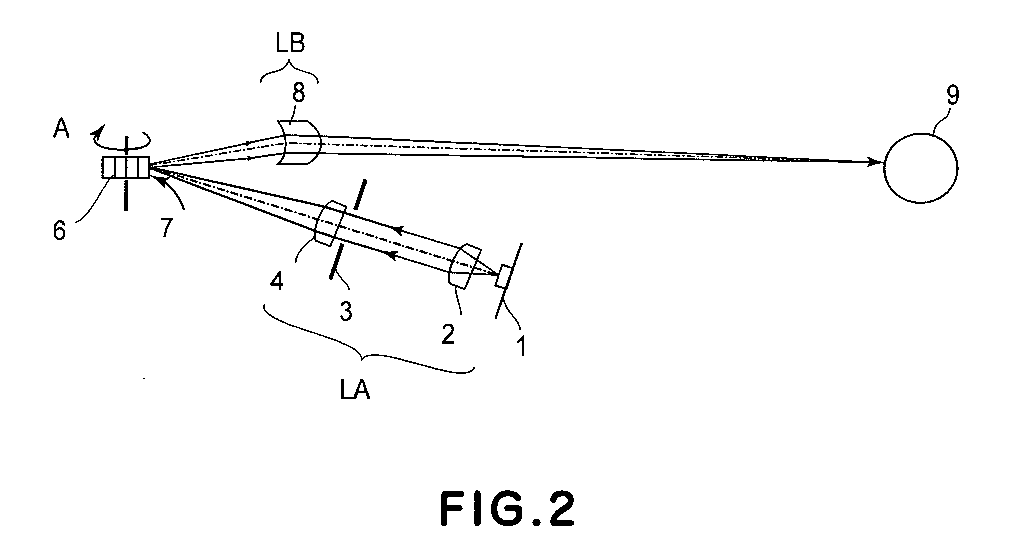
[0050]FIG. 1 is a sectional view along a main-scan direction (main-scan sectional plane) of a main portion of a first embodiment of the present invention. FIG. 2 is a sectional view along a sub-scan direction (sub-scan sectional plane) of the same.
[0051] Here, in FIG. 2, for better understanding, a flat mirror 5 shown in FIG. 1 is not illustrated and, therefore, the light path shown there is not bent by the flat mirror 5.
[0052] In this specification, the term “main-scan direction” refers to a direction which is perpendicular to the rotational axis of a rotary polygonal mirror and to the optical axis of an imaging optical system (that is, a direction in which a light beam is reflectively deflected (deflectively scanned) by the rotary polygonal mirror). The term “sub-scan direction” refers to a direction which is parallel to the rotational axis of the rotary polygonal mirror. The term “main-scan sectional plane” refers to a plane that contains the main-scan direction a...
embodiment 2
[Embodiment 2]
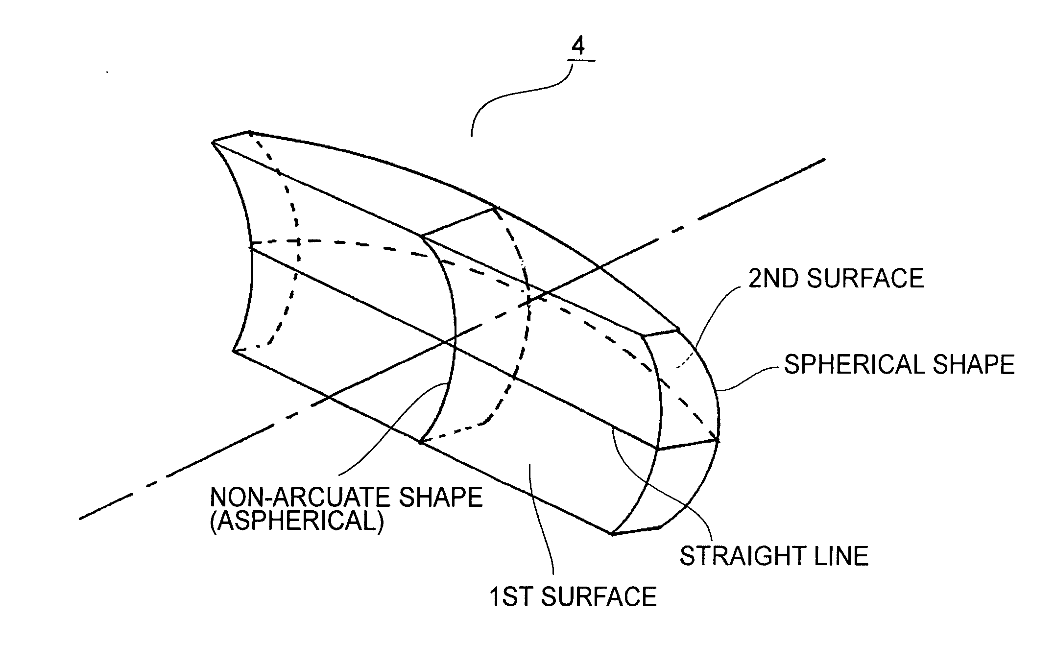
[0088]FIGS. 6A and 6B illustrate sectional views, along the main-scan sectional plane and the sub-scan sectional plane, respectively, of a collecting lens or collimator lens 64 according to a second embodiment of the present invention.
[0089] This embodiment differs from the first embodiment in that the second surface (light exit surface) of the collecting lens 64 has a different shape. The structures and optical functions of the remaining portion of this embodiment are essentially the same as those of the first embodiment, and hence similar advangeous results are obtainable with this embodiment.
[0090] More specifically, in the first embodiment, the second surface of the collecting lens is defined by a spherical shape. In this embodiment, as compared therewith, the second surface is defined by a non-arcuate shape being rotationally symmetric, both in the main-scan sectional plane and in the sub-scan sectional plane. This is to completely compensate the spherical aberr...
embodiment 3
[Embodiment 3]
[0094]FIGS. 8A and 8B illustrate sectional views, along the main-scan sectional plane and the sub-scan sectional plane, respectively, of a collecting lens or collimator lens 84 according to a third embodiment of the present invention.
[0095] This embodiment differs from the first embodiment in that the first and second surfaces of the collecting lens 64 have different shapes. The structures and optical functions of the remaining portion of this embodiment are essentially the same as those of the first embodiment, and hence similar advangeous results are obtainable with this embodiment.
[0096] More specifically, in this embodiment, the first surface of the collecting lens 84 is defined by a flat surface shape in the main-scan direction and the sub-scan direction, while the second surface thereof is defined by a rotationally asymmetrical shape and yet, in the main-scan sectional plane and the sub-scan sectional plane, a non-arcuate shape. Here, it should be noted that th...
PUM
 Abstract
Description
Claims
Application Information