Phosphorescent organic light-emitting diodes

a light-emitting diode and organic technology, applied in the direction of discharge tube/lamp details, luminescnet screen, discharge tube/lamp details, etc., can solve the problems of complicated process, serious delay in research and development of blue phosphorescent pixels compared to red and green phosphorescent pixels, and difficult phosphorescent molecules synthesis

Inactive Publication Date: 2007-04-26
AU OPTRONICS CORP
View PDF12 Cites 13 Cited by
  • Summary
  • Abstract
  • Description
  • Claims
  • Application Information

AI Technical Summary

Problems solved by technology

At first, synthesis of phosphorescent molecules, especially blue and green light-emitting phosphorescent molecules, is more difficult than conventional fluorescent organic molecules.
A full color panel requires R, G, B pixels arranged in side by side manner, but the research and development of blue phosphorescent pixels are seriously delayed compared to red and green phosphorescent pixels.
A challenge to process integration is that the manufacture of phosphorescent pixels requires an additional evaporation chamber for HBL, which complicates the process, and increases the cost and time.
With N-type host light-emitting materials, however, process integration with pixels using conventional P-type host light-emitting materials is difficult.

Method used


Image

  • Phosphorescent organic light-emitting diodes
  • Phosphorescent organic light-emitting diodes
  • Phosphorescent organic light-emitting diodes

Examples


example 1

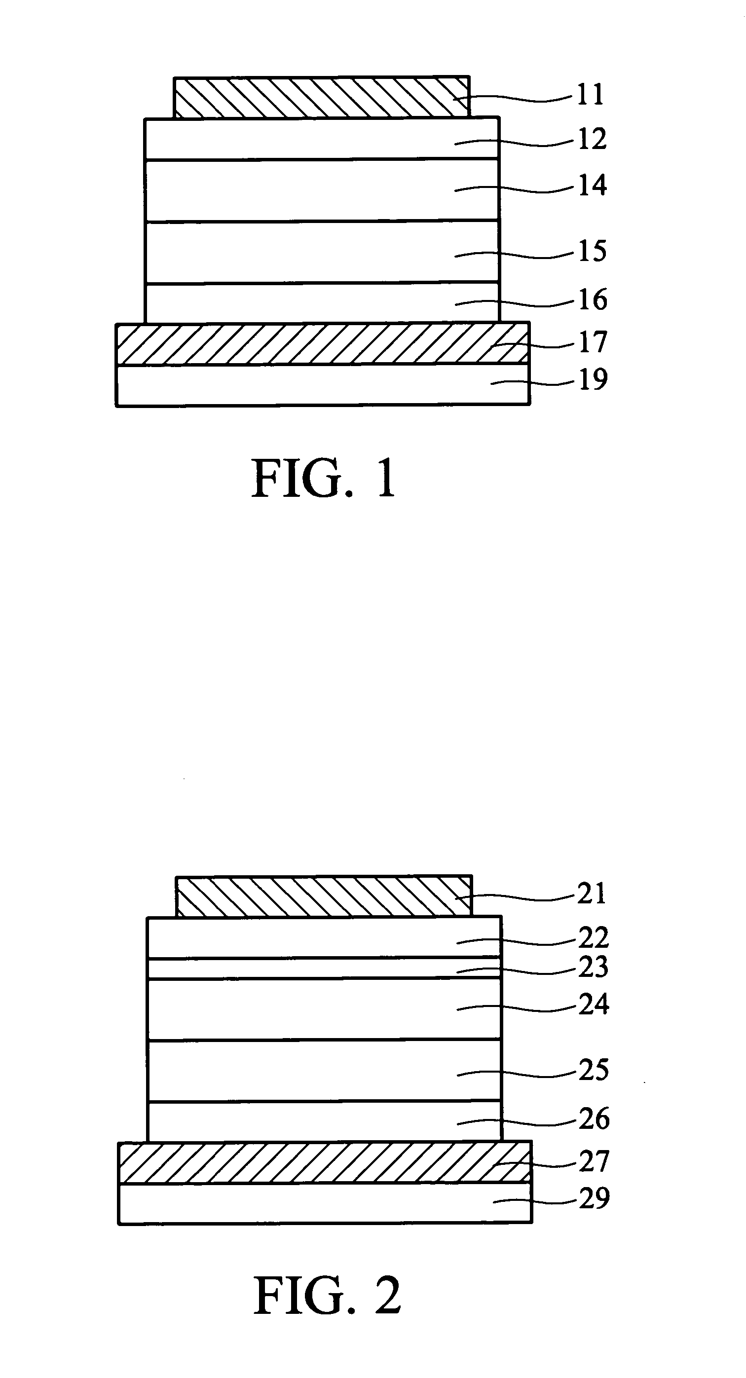
[0029]FIG. 1 shows a cross section view of Examples 1-3.

[0030] Anode 17: indium tin oxide (ITO) of about 700 angstroms on a glass substrate 19;

[0031] HIL 16: 4,4′,4″-tri(N-(2-naphthyl)-N-aniline)-triphenyl amine (2T-NATA) of about 150 nm;

[0032] HTL 15: N,N′-di-1-naphthyl-N,N′-diphenyl-1,1′-biphenyl-1,1′-biphenyl-4,4′-diamine (NPB) of about 600 angstroms;

[0033] light-emitting layer 14: CBP (phosphorescent host material) and BAlq (exiton blocking material) had a volume ratio of 70:30, and a red phosphorescent dopant had 15% volume ratio of the light-emitting layer; and the light-emitting layer had a thickness of 550 angstroms;

[0034] ETL 12: Alq3 of 300 nm;

[0035] EIL (not shown): LiF of 10 angstroms; and

[0036] cathode 11: Al of 200 nm.

example 2

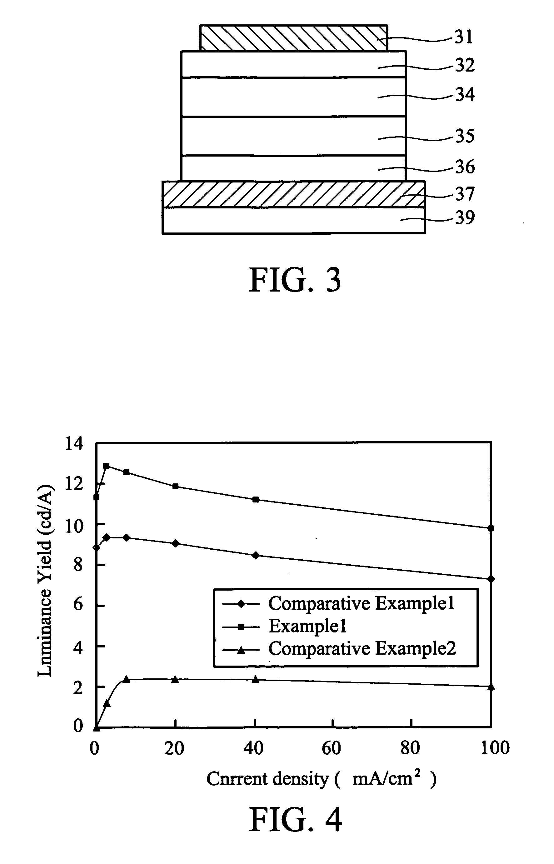
[0037] Anode 17: indium tin oxide (ITO) of about 700 angstroms on a glass substrate 19;

[0038] HIL 16: 2T-NATA of about 150 nm;

[0039] HTL 15: NPB of about 600 angstroms;

[0040] light-emitting layer 14: CBP (phosphorescent host material) and BAlq (exiton blocking material) had a volume ratio of 70:30, and a green phosphorescent dopant had 8% volume ratio of the light-emitting layer; and the light-emitting layer had a thickness of 550 angstroms;

[0041] ETL 12: Alq3 of 300 nm;

[0042] EIL (not shown): LiF of 10 angstroms; and

[0043] cathode 11: Al of 200 nm.

example 3

[0044] Anode 17: indium tin oxide (ITO) of about 700 angstroms on a glass substrate 19;

[0045] HIL 16: 2T-NATA of about 150 nm:

[0046] HTL 15: NPB of about 600 angstroms;

[0047] light-emitting layer 14: CBP (phosphorescent host material) and BAlq (exiton blocking material) had a volume ratio of 70:30, and a blue phosphorescent dopant had 12% volume ratio of the light-emitting layer; and the light-emitting layer had a thickness of 550 angstroms;

[0048] ETL 12: Alq3 of 300 nm;

[0049] EIL (not shown): LiF of 10 angstroms; and

[0050] cathode 11: Al of 200 nm.


PUM

PropertyMeasurementUnit
thicknessaaaaaaaaaa
thicknessaaaaaaaaaa
thicknessaaaaaaaaaa

Abstract

A phosphorescent OLED has a light emitting layer which includes a phosphorescent host material, an exiton blocking material, and a phosphorescent dopant. The invention obviates the use of a hole blocking layer while substantially preventing hole diffusion to the electron transport layer.

Description

BACKGROUND OF THE INVENTION [0001] 1. Field of the Invention [0002] The invention relates to organic light-emitting devices, and in particular relates to phosphorescent light-emitting devices and its application. [0003] 2. Description of the Related Art [0004] Organic light-emitting diodes (OLED) are based on organic molecules. The quantum yield of phosphorescent materials (theoretical yield 100%) is higher than that of conventional fluorescent materials (theoretical yield 25%), and therefore the phosphorescent materials may retain luminance for a long time after terminating excitation. Phosphorescent organic light-emitting devices, however, must overcome two major obstacles. At first, synthesis of phosphorescent molecules, especially blue and green light-emitting phosphorescent molecules, is more difficult than conventional fluorescent organic molecules. Second, when the excitation energy diffuses from the light-emitting layer to other layers, it induces color impurity and light el...

Claims


Application Information

Patent Timeline
Patent Type & Authority Applications(United States)
IPC IPC(8): H01L51/54
CPCH01L27/3211H01L51/006H01L51/0071H01L51/0072H01L51/0081H01L51/5016H10K59/35H10K85/633H10K85/657H10K85/324H10K85/6572H10K50/11H10K2101/10
Inventor LIU, TSWEN-HSIN
Owner AU OPTRONICS CORP
Why Eureka
Try Eureka