Systems and methods for generating laser light shaped as a line beam

a laser light and line beam technology, applied in the field of system and method for generating laser light as a line beam, can solve the problems of critical block edge damage, block collision, and unsatisfactory crystal quality of new grains

Inactive Publication Date: 2007-05-03
CARL ZEISS SMT GMBH +1
View PDF9 Cites 92 Cited by
  • Summary
  • Abstract
  • Description
  • Claims
  • Application Information

AI Technical Summary

Problems solved by technology

More specifically, failure to obtain a steep sidewall on the trailing short-axis edge may result in the undesirable crystal quality of new grains near the short-axis edge due to insufficient overlap between adjacent pulses.
Thus, this slightest error in positioning can cause the blocks to collide and damage the critical block edges which define the slit shaped element.
Large amounts of heat can distort the critical block edges which define the slit shaped element, and if severe, cause undesirable aberrations in the laser beam.

Method used


Image

  • Systems and methods for generating laser light shaped as a line beam
  • Systems and methods for generating laser light shaped as a line beam
  • Systems and methods for generating laser light shaped as a line beam

Examples


Embodiment Construction

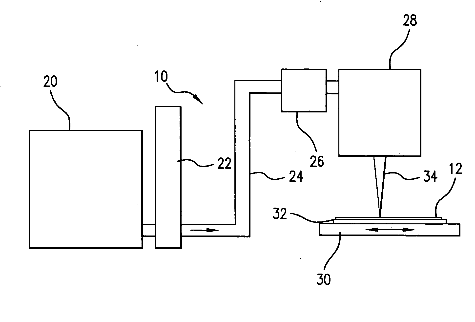
[0018] Referring initially to FIG. 1, there is shown a schematic, not to scale, view of the primary components of a production system, designated generally system 10, for crystallizing an amorphous silicon film 12. As shown, the system 10 may include a laser source 20 for generating a pulsed laser beam, a pulse stretcher 22 for increasing pulse duration and a beam delivery unit 24 which may have a mechanism to actively steer the beam and / or an active beam expander.

[0019] In overview, the laser source 20 may be a two chamber laser having a power oscillator and a power amplifier, and accordingly, is often referred to as a so-called POPA laser source. In one implementation of the crystallization process described above, a 6 Khz (6000 pulses per second) POPA laser may be used with pulse energies of approximately 150 mJ. With this arrangement, a 730 mm×920 mm film may be processed (with 60 percent overlap) in about 75 seconds. The power oscillator and the power amplifier each comprise a...


PUM


Abstract

Systems and methods are disclosed for shaping a laser beam for interaction with a film in which the laser beam travels along a beam path and defines a short-axis and a long-axis. In one aspect, the system may include a first short-axis element having an edge positioned at a distance, d1, along the beam path from the film and a second short-axis element having an edge positioned at a distance, d2, along the beam path from the film, with d2<d1. An optic may be positioned along the beam path between the second element and the film for focusing the beam in the short-axis for interaction with the film. In another aspect, a system may be provided having a mechanism operative to selectively adjust the curvature of one or both of the edges of the short-axis element.

Description

CROSS-REFERENCE TO RELATED APPLICATIONS [0001] The present invention is related to U.S. application Ser. No. 10 / 781,251, titled “VERY HIGH ENERGY, HIGH STABILITY GAS DISCHARGE LASER SURFACE TREATMENT SYSTEM,” filed on Feb. 18, 2004, to U.S. application Ser. No. 10 / 884,101, titled “LASER THIN FILM POLY-SILICON ANNEALING OPTICAL SYSTEM,” filed on Jul. 1, 2004, and to U.S. application Ser. No. 11 / 138,001, titled “SYSTEMS AND METHODS FOR IMPLEMENTING AN INTERACTION BETWEEN A LASER SHAPED AS A LINE BEAM AND A FILM DEPOSITED ON A SUBSTRATE” filed on May 26, 2005, the disclosures of each of which are hereby incorporated by reference herein.FIELD OF THE INVENTION [0002] The present invention relates to systems and methods for generating laser light shaped as a line beam. Uses of laser light shaped as a line beam may include, but are not necessarily limited to, the melting of an amorphous silicon film to induce crystallization of the film upon resolidification of the melted segment, for the ...

Claims


Application Information

Patent Timeline
Patent Type & Authority Applications(United States)
IPC IPC(8): G02B27/10
CPCG02B7/004G02B27/095G02B27/0977G02B27/0988G02B19/0009G02B19/0052G02B19/0028
Inventor DAS, PALASH P.CEFALO, ALBERT P.KNOWLES, DAVID S.SHKLOVER, VITALIYMUENZ, HOLGER
Owner CARL ZEISS SMT GMBH
Why Eureka
Try Eureka