Method and apparatus for measuring optical power of very weak light, and optical communication system using the same

a technology of optical power and optical communication system, applied in the field of measuring the optical power of light, can solve problems such as interfering with each other, and achieve the effects of stable information transmission, high-speed and stable quantum key distribution

Active Publication Date: 2007-05-03
NEC CORP
View PDF11 Cites 26 Cited by
  • Summary
  • Abstract
  • Description
  • Claims
  • Application Information

AI Technical Summary

Benefits of technology

[0020] Another object of the present invention is to provide an optical communication system that optimizes the timing in the sender by using the weak-light power measurement method and thus enables information to be stably transmitted at right timing.
[0021] Still another object of the present invention is to provide an optical communication system that drives the phase modulator on the sender side at right timing and thus enables high-speed, stable quantum key distribution.
[0025] Since the optical power or similar physical quantity of very weak light can be measured by a photon detector in the above manner, an optical transmitter in an optical communication system can be operated at optimal timing, resulting in stable information transmission. In the case of the present invention being applied to a quantum key distribution system, a phase modulator at a transmitting side can be operated at right timing, resulting in high-speed and stable quantum key distribution.

Problems solved by technology

As a whole, the two pulses pass along the same optical path and then interfere with each other.
However, in the case of the gated-Geiger-mode reception, bias is applied to a photon detector APD only for a predetermined period of time, at the timing of the arrival of an optical pulse.

Method used


Image

  • Method and apparatus for measuring optical power of very weak light, and optical communication system using the same
  • Method and apparatus for measuring optical power of very weak light, and optical communication system using the same
  • Method and apparatus for measuring optical power of very weak light, and optical communication system using the same

Examples


first embodiment

1. First Embodiment

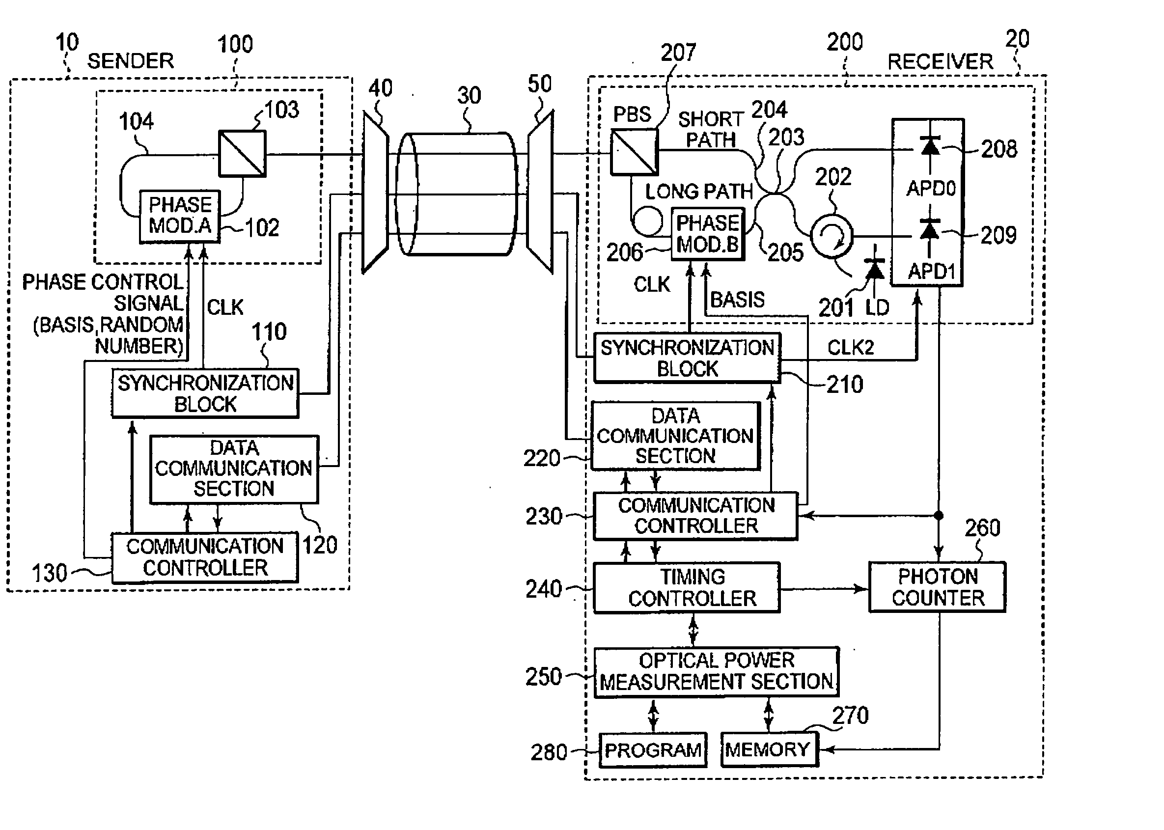
[0056]FIG. 5 is a block diagram showing a configuration of a temperature-independent plug and play system according to a first embodiment of the present invention. Here, the system configuration is illustrated as an example, in which, of two communication devices that perform quantum communications, the sending side of the quantum communications is referred to as a sender 10, the receiving side thereof is referred to as a receiver 20, and the sender 10 and receiver 20 are optically connected through an optical transmission line 30.

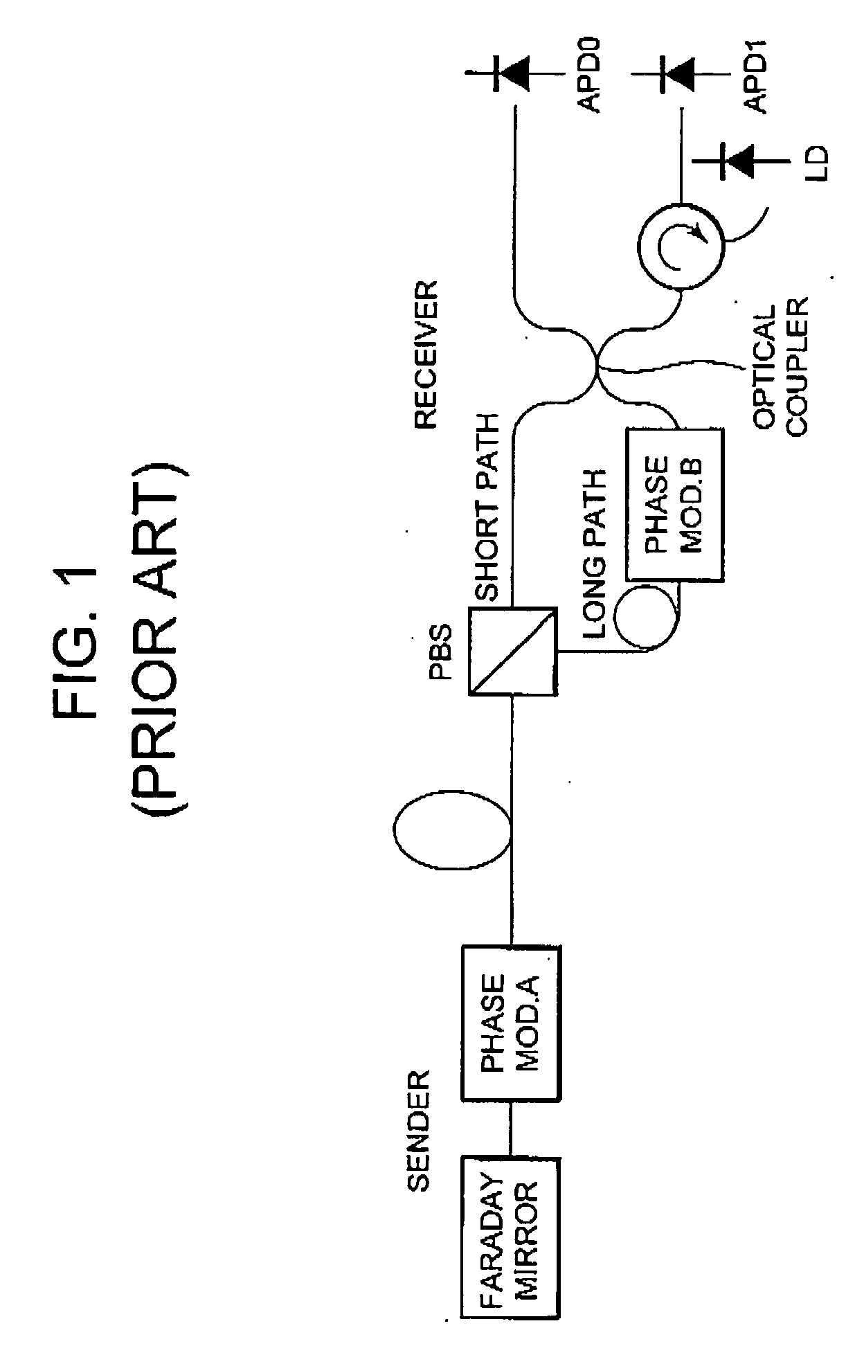
[0057] The basic configuration and operations of the plug and play system according to the first embodiment are as described with reference to FIG. 1, except that a PBS loop is employed at the sender 10 in place of a Faraday mirror.

[0058] A quantum block 100 at the sender 10 has a PBS loop 104, which includes a phase modulator 102 and a polarization beam splitter (PBS) 103.

[0059] The phase modulator 102 performs phase modulation on a ...

second embodiment

2. Second Embodiment

[0123]FIG. 12 is a flowchart showing a procedure of the control of the sender's timing, in a quantum cryptographic system according to a second embodiment of the present invention. The block configuration of the quantum cryptographic system according to the second embodiment is similar to that of the first embodiment as shown in FIG. 5. The optical pulses to be sent and received behave as in the first embodiment, as described based on FIGS. 6 and 7. Therefore, a description of the parts overlapping with the first embodiment will be omitted. With reference to FIGS. 5 and 12, operations of determining the extinction ratio, of searching for the sender's clock timing, and of determining the optimal timing will be described in detail.

2.1) Measurement of Extinction Ratio

[0124] The timing controller 240 controls the communication controller 230 so that one of the four combinations of a basis and a random number is selected, that the selected basis is set on the phase...

third embodiment

3. Third Embodiment

[0158] As described above, according to the second embodiment, each time the clock signal CLK2 is shifted by one step, the count value made by the photon counter 260 and the then amount of the phase shift are stored in the memory 270, associated with each other. According to a third embodiment, by utilizing this data stored in the memory 270, not only the extinction ratio can be measured, but also the optimal timing can be determined for each of the sender and the receiver. Hereinafter, the third embodiment will be described in detail.

[0159]FIG. 14 is a flowchart showing a procedure of the control of the sender's timing, in a quantum cryptographic system according to the third embodiment of the present invention. The block configuration of the quantum cryptographic system according to the third embodiment is similar to that of the first embodiment as shown in FIG. 5. The optical pulses to be sent and received behave as in the first embodiment, as described based ...


PUM


Abstract

A method and apparatus for measuring the optical power of very weak light arriving at a receiver, by using a photon detector, are provided. A photon detector detects the presence or absence of the arrival of a photon in accordance with bias application timing. For a train of optical pulses coming in at an arbitrary timing in respective time slots, the bias application timing is sequentially shifted within the range of a time slot. Each time a shift is made, the number of photons detected is counted by a photon counter. Based on this number of photons, the optical power of the train of the optical pulses is measured.

Description

BACKGROUND OF THE INVENTION [0001] 1. Field of the Invention [0002] The present invention relates to techniques of measuring the optical power of light and, more particularly, to a method and apparatus for measuring the optical power of very weak light and an optical communication system using the method. [0003] 2. Description of the Related Art [0004] In the field of optical communications, in recent years, active studies have been devoted to quantum key distribution systems, which are regarded as realizing the high secrecy along a transmission line, and a variety of proposals have been made in regard to the systems. [0005] As a basic one of the systems, a system which allows a sender and a receiver to share a quantum cryptographic key by using two types of bases is proposed in Bennett and brassard, “QUANTUM CRYPTOGRAPHY, PUBLIC KEY DISTRIBUTION AND COIN TOSSING” IEEE International Conference on Computers, Systems, and Signal Processing, Bangalore, India, pp. 175-179. According to ...

Claims


Application Information

Patent Timeline
Patent Type & Authority Applications(United States)
IPC IPC(8): H04B10/08H04B10/556H04B10/07H04B10/25H04B10/524H04B10/70H04L9/12
CPCH04B10/66H04L9/0852
Inventor MAEDA, WAKAKOTAJIMA, AKIOTANAKA, AKIHIROTAKAHASHI, SEIGO
Owner NEC CORP
Why Eureka
Try Eureka