
Safety catheter system and method

a catheter and safety technology, applied in the field of intravenous catheters, can solve the problems of skin raising the possibility of infection, medical personnel may inadvertently puncture herself or herself, and the needle is extremely sharp, so as to reduce the possibility of operator being punctured with the sharp tip

Active Publication Date: 2007-05-03
CAREFUSION 303 INC
View PDF95 Cites 96 Cited by
  • Summary
  • Abstract
  • Description
  • Claims
  • Application Information

AI Technical Summary

Benefits of technology

[0017] In another aspect, the needle tube comprises a locking device to retain the needle in a retracted position within the needle tube once the sharp needle has been retracted. The locking device permanently retains the sharp tip of the needle within the tube to protect clinicians against being punctured by the needle. In another aspect, the movable element includes a head having a bore through which fluid flows through the connector. The bore is marquise-shaped and is naturally open. The connector includes a larger inner diameter section at the second position of the movable element such that the bore may resume its naturally open configuration and permit fluid flow through the connector and the catheter.
[0018] In accordance with method aspects of the invention, there is provided a method for providing access to a biological site through placement of a catheter in the site. The method comprises moving a blunt cannula into a first port of a connector into contact with a movable element of the connector to move the movable element into a housing of the connector to a position where the movable element opens to permit flow of fluid through the connector, the blunt cannula also moving into the opening of the movable element to provide protection to the movable element, sliding a needle having a sharp tip through the blunt cannula and through a catheter connected to the connector so that the sharp tip of the needle extends beyond the catheter a sufficient length that enables an operator to access a biological site with the sharp needle and catheter retracting the sharp needle from the catheter and the blunt cannula, removing the blunt cannula from the connector, and moving the movable element of the connector to a closed position at which the movable element prevents flow of fluid through the catheter.
[0019] In accordance with more detailed aspects, the method further comprises the step of protecting the sharp tip of the needle with a physical barrier whereby the possibilities of a operator being punctured with the sharp tip are reduced. Further, the of moving a blunt cannula into a first port of a connector into contact with a movable element comprises moving the movable element into a second position within a housing of the connector at which position a bore through the movable element resumes its naturally open shape providing a fluid flow passageway through the connector, and moving the blunt cannula into the bore of the movable element to provide protection to the movable element. Additionally, the method further comprises the steps of limiting the movement of the blunt cannula to a position within the connector to entering the open bore, and restraining the sharp needle tip from projecting beyond an end of the blunt cannula before the blunt cannula reaches the limit of its movement.

Problems solved by technology

Such needles are extremely sharp and should the insertion site become wet with administration fluid or blood, the medical personnel may inadvertently puncture herself or himself while handling the sharp needle.
Any opening in the skin raises the possibility of contracting an infection.
While this approach has advanced the safety of health care workers substantially, a venipuncture procedure still requires the use of a sharp needle.
During the above venipuncture procedure, medical personnel are exposed to the possibility of an accidental needle puncture or to contamination from the back flow of the patient's blood from the venipuncture site.
However, a problem that may result from such an assembly using a pre-slit septum in the connector / catheter device is the possibility of damage to the septum due to the blunt cannula being repeatedly forced into the normally closed pre-slit septum.
A damaged septum may leak blood and this may then expose a health care provider to any infectious diseases contained in the blood.
A further problem that may arise during the use of such an assembly is that some guarded needle devices available today are somewhat complex with multiple stops and locking devices designed to protect the medical personnel from needle punctures.
Unfortunately, the action of sliding the needle into the fluid path created by the blunt cannula and the pre-slit septum with these complex devices may require more than one physical hand movement by the medical personnel operating the assembly.
Because medical personnel are quite busy, any additional efforts required to accomplish tasks are undesirable.
Further, the requirement of extremely fine motor skills during the placement of a sharp needle in a catheter and into a patient can result in inadvertent damage to the connector of the catheter resulting in blood leakage.
Pre-slit septum systems also do not typically allow access to the catheter with standard male Luer connectors.
An adapter is required, which is not desirable.
In addition to the expense of an additional part, such adapters can get lost or may not be in stock when needed.

Method used


Image

  • Safety catheter system and method
  • Safety catheter system and method
  • Safety catheter system and method

Examples


Embodiment Construction

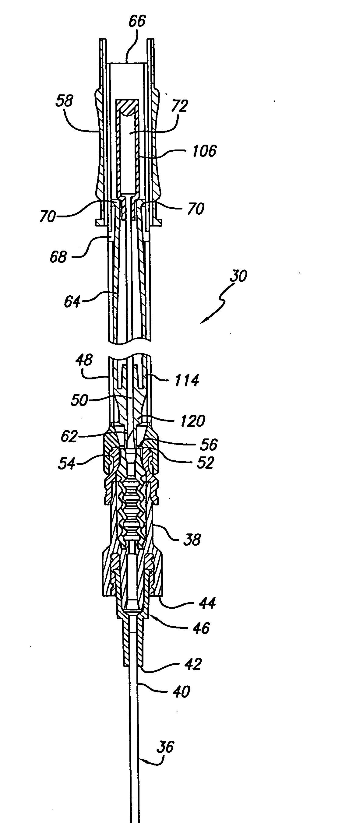
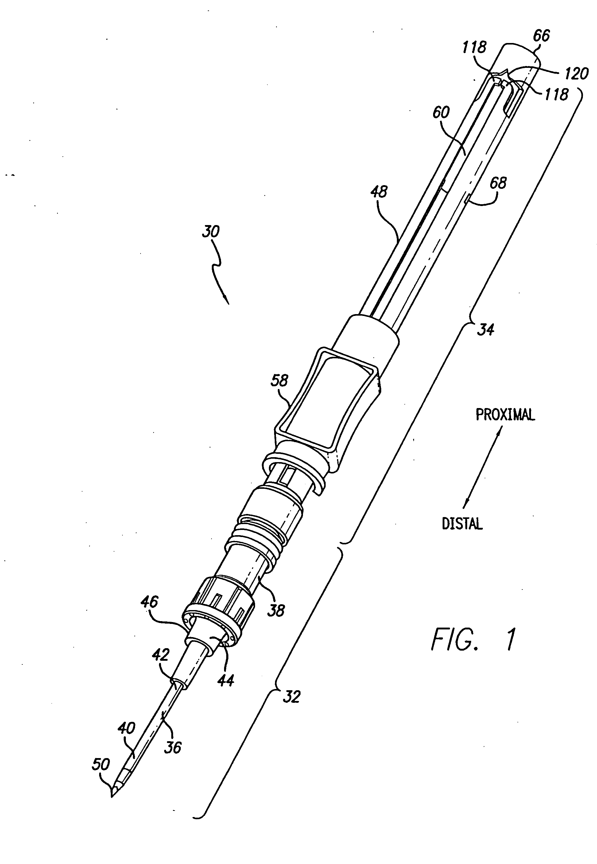
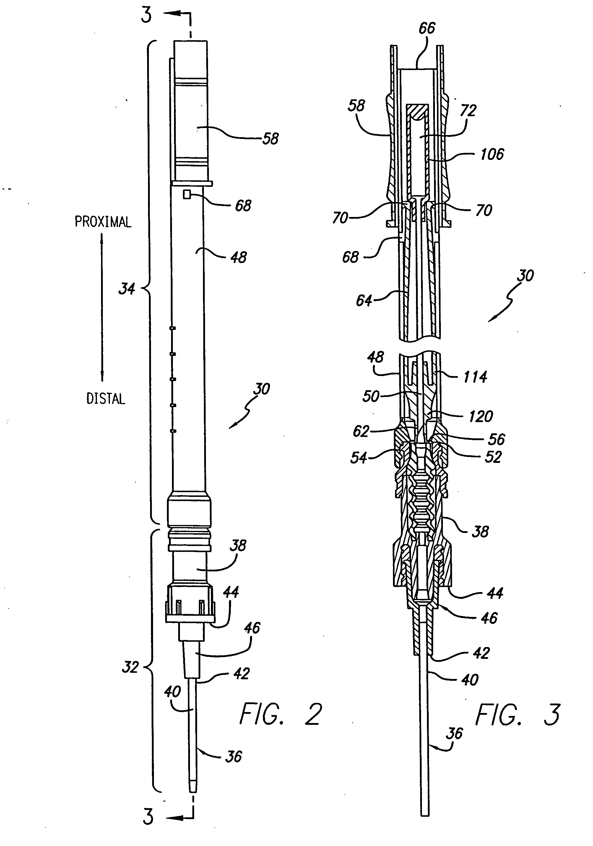
[0039] Referring now to the drawings in which like reference numerals indicate like or similar elements among the several views, FIGS. 1, 2, and 3 show different views of an intravenous safety catheter insertion device 30 comprising a safety catheter device 32 to which is mounted an insertion mechanism 34. The safety catheter device 32 comprises a catheter 36 and a valved connector 38 mounted to the catheter. The catheter 36 is of a conventional type well known in the art, and comprises a soft flexible body or tube 40 made from plastic or silicone mounted at its proximal end 42 to the distal end 44 of the connector 38. In this embodiment, the catheter tube 40 is connected to the connector 38 with a female Luer adapter 46. The catheter tube 40 is generally between 19 mm (0.75 inches) and 31.75 mm (1.25 inches) in length and between 16 and 24 gauge in diameter, although other sizes may be used. The insertion mechanism 34 comprises a needle tube 48 within which is housed a sharp needle...


PUM


Abstract

A catheter integral with a valved needle-free connector provides a safety catheter device configured to receive a blunt cannula and sharp needle forming an insertion mechanism. The sharp needle is mounted within a needle tube and a control handle is used to slide the sharp needle out of and into the protective needle tube. When the insertion mechanism is mounted to the connector and the control handle is used to slide the sharp needle out of the tube, a blunt cannula first moves into contact with and enters the bore of the valve mechanism of the connector opening it and protecting it from damage that may be caused by the sharp needle. The sharp needle is then extended through the connector and extends out the distal end of the catheter so that a venipuncture procedure may be performed to properly locate the catheter in the patient's circulatory system. Once located, the needle may be retracted into the insertion mechanism, the insertion mechanism disconnected from the connector, and discarded.

Description

BACKGROUND [0001] The present invention relates generally to intravenous catheters, and more particularly to an intravenous catheter having a connector operable with a blunt cannula to control the flow of fluid through the IV catheter. [0002] Intraveńious (IV) therapy is a versatile technique used for the administration of medical fluids to patients. It has been used for various purposes such as the maintenance of fluid and electrolyte balance, the transfusion of blood, the administration of nutritional supplements, chemotherapy, and the administration of drugs and medications. Fluids may be administered intravenously by injection through a hypodermic syringe, or intermittently or continuously by infusion using a needle or a plastic or silicone catheter. [0003] Although there are many advantages to be derived by the patient from the intravenous administration of fluids, the past two decades have brought heightened awareness of the risks of propagating infectious diseases associated ...

Claims


Application Information

Patent Timeline
Patent Type & Authority Applications(United States)
IPC IPC(8): A61M5/178A61M25/06A61M39/04A61M39/26
CPCA61M25/0631A61M25/0693A61M39/045A61M39/26A61M2039/262A61M2039/263
Inventor LEINSING, KARL R.SHUTE, MATTHEW R.
Owner CAREFUSION 303 INC
Learn More