Compound bows

Inactive Publication Date: 2007-05-10
STEVENS SIMS INC
View PDF7 Cites 53 Cited by
  • Summary
  • Abstract
  • Description
  • Claims
  • Application Information

AI Technical Summary

Benefits of technology

[0027] Yet another important advantage of the present invention is realized by elimination of the buss system employed in a conventional compound bow. This system has buss cables fixed to the extreme ends of the bow; specifically, at the outermost ends of the flexible bow limbs and to buss cams which rotate with the string cams. When the bow is drawn, the buss cables place the bow's riser, especially its central, hand grip segment, under a very large load, creating a correspondingly large bending moment in the riser. The elimination of a buss cable system in the bows disclosed herein eliminates such stress, allowing the riser to be made significantly lighter than a riser of conventional construction because the only load placed on the riser is that of the bow string. At the same time, the riser is less susceptible to distortion, even if lighter; and the precision with which an arrow can be shot is correspondingly increased.
[0028] The force-generating components of the power units employed herein may be attached with a simple adjusting screw mechanism which both allows the bow to be readily disassembled for string and component replacement, even in the field, and makes it equally simple to adjust the force required to draw the bow from essentially zero up to the typical maximum of 70 pounds. No bow press is needed, and the force-generating components are so small that spares can be slipped into an archer's pocket. These are significant practical advantages, especially to a bow hunter.
[0029] Because they are so small and are elastically deformed to only a very limited extent, even at full draw of the bow in which they are incorporated, the force-generating components disclosed herein are highly resistant to breakage, even if the bow is dry fired or the bow string is cut in the course of loading a broadhead or other sharp arrow; and these force-generating components can be easily shrouded so that, in the unlikely event one breaks, parts which come loose will be contained instead of flying around and possibly hitting and injuring the archer. This eliminates a serious drawback of conventional compound bows which, when a limb breaks, may leave parts of the limb flying like a missile or flailing around on the bow string. The bows of the present invention are therefore safer to shoot than conventional compound bows are, and product liability is significantly less of a problem for manufacturers and sellers. Also, because they are shroude

Problems solved by technology

However, these cams are rotatably mounted to opposite ends of the rigid riser rat

Method used


Image

  • Compound bows
  • Compound bows
  • Compound bows

Examples


Embodiment Construction

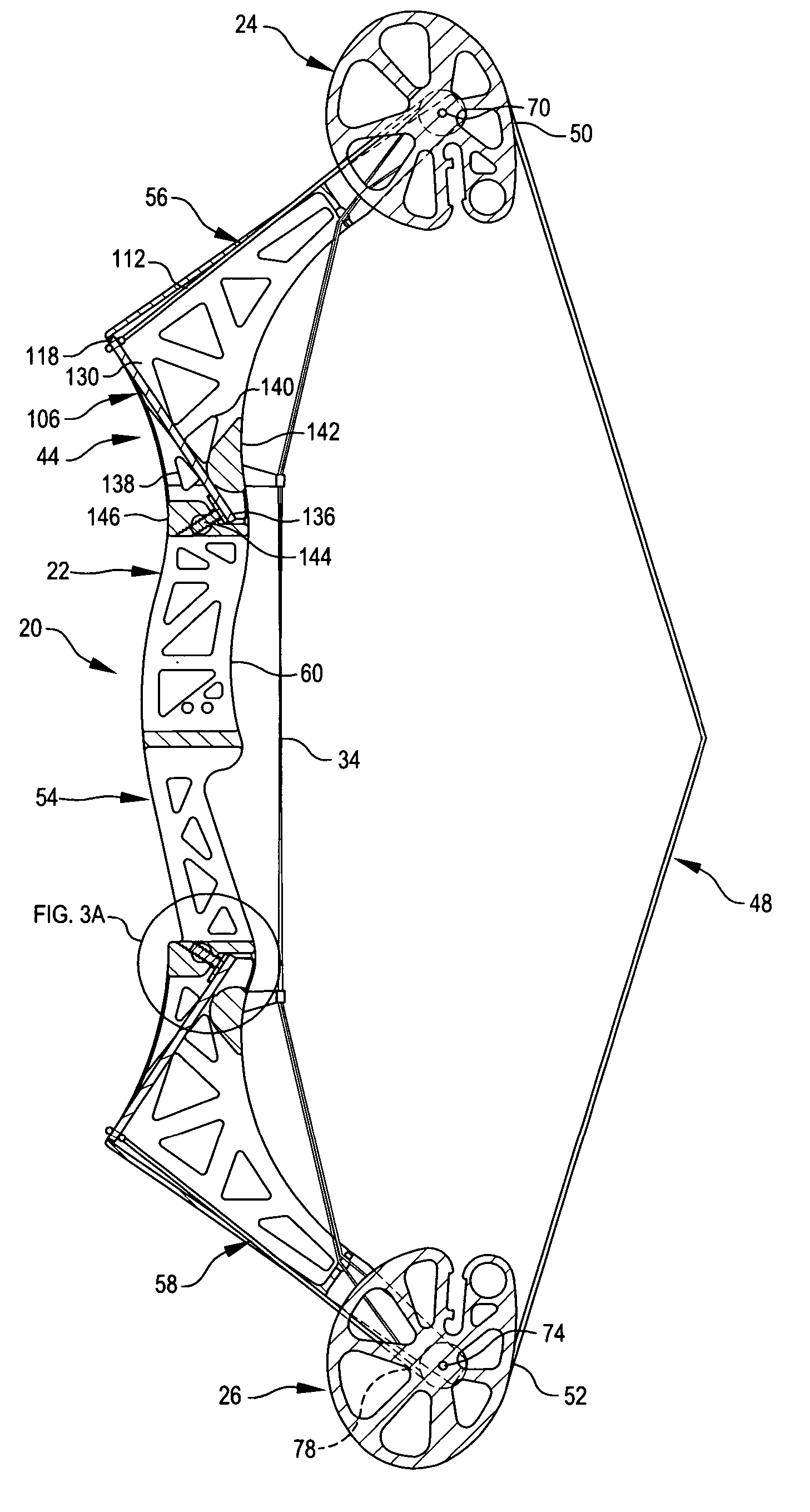
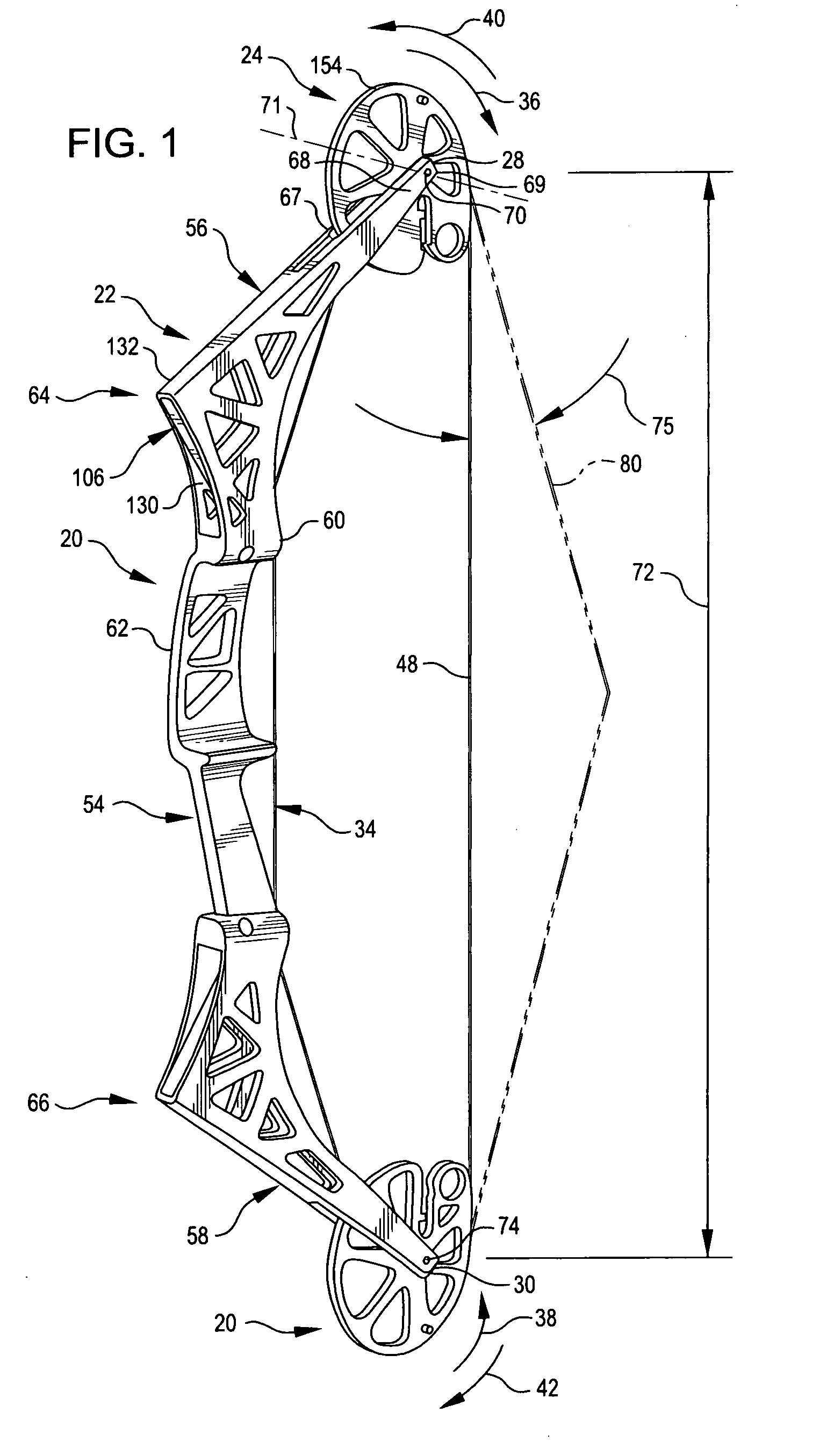
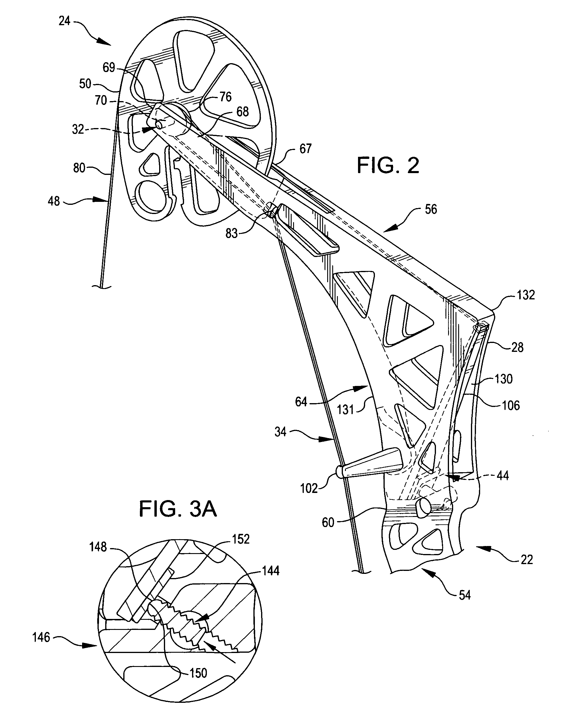
[0060] Referring now to the drawings, FIGS. 1 and 2 depicts a compound archery bow 20 constructed in accord with and embodying the principles of the present invention. The major components of bow 20 include an elongated, rigid riser 22; string cams 24 and 26 at the upper and lower ends 28 and 30 of riser 22; a timing system 32 (see especially FIGS. 6-8), including a timing cable 34 for synchronizing the counter rotation of string cams 24 and 26 suggested by arrows 36 / 38 and 40 / 42 in FIG. 1; and riser-mounted power units 44 and 46 (see especially FIGS. 3-6) which store arrow propelling energy in potential form as bow 20 is drawn. A bow string 48 extends between and is connected at its opposite ends 50 and 52 to the upper and lower string cams 24 and 26. With the components of bow 20 in their rest configurations and positions, bow string 48 lies along a straight line located to the rear of riser center section 54. When bow 20 is fully drawn, bow string 48 is configured as shown in pha...


PUM


Abstract

Improved compound bows which are smaller, more compact, lighter, and more easily handled and serviced than compound bows of conventional construction but are nevertheless capable of propelling an arrow at an equal or higher velocity and with comparable or greater accuracy than a conventional bow. The improved bows are quieter than those of conventional construction and less apt to snag on brush or other obstacles. They have a rigid riser with ends to which string cams are rotatably mounted and cam-associated power units mounted to and towards the ends of the riser. Each power unit has a component which is elastically deformed to store potential energy as the bow is drawn and a power cable connecting the power storing component to the associated string cam. A bow string extends between and is connected at its opposite ends to the string cams. As the bow is drawn, the string cams are rotated in counter directions, pulling on the power unit cables and thereby elastically deforming and storing potential energy in the power unit components. When the bow string is subsequently released, the elastically deformable power unit components restore to rest configurations, this converting the stored potential energy to arrow propelling kinetic energy. A timing cable arrangement insures that the cams are synchronized to rotate in unison, avoiding the unwanted nock travel that might otherwise occur; and the power units have an adjustment feature which allows the force required to fully draw the bow to be changed.

Description

TECHNICAL FIELD OF THE INVENTION [0001] The present invention relates to novel, improved, compound archery bows. BACKGROUND OF THE INVENTION [0002] The compound bow is a relatively recent development. It has been reported that the first patent on a compound bow is U.S. Pat. No. 3,486,495 issued 30 Dec. 1969. [0003] Modern compound bows are instruments of considerable sophistication and not insignificant complexity. [0004] A bow of this type has a rigid riser with a grip for the archer and flexible limbs extending in opposite directions from the two, opposite ends of the riser. A rotatable cam and a wheel (single cam bow) or two rotatable cams (double cam bow) are mounted to and move with the extreme ends of the flexible bow limbs as the bow is drawn and as the bow string is subsequently released. [0005] A bow string is connected between the cams, which rotate in opposite directions when the bow is drawn. As the bow is drawn, the bow string moves away from the limb / riser assembly of ...

Claims


Application Information

Patent Timeline
IPC IPC(8): F41B5/10
CPCF41B5/10F41B5/105
Inventor SIMS, STEVENMERRIMAN, ARDENSEIL, JOHNATHAN F.SIMS, GARYWINTERS, GREG
Owner STEVENS SIMS INC
Why Eureka
Try Eureka