Manufacturing method for printing circuit

a printing circuit and manufacturing method technology, applied in patterning, patterning, lithography/patterning, etc., can solve the problems of high production cost, inability to meet the needs of customers, so as to save production cost and simplify the manufacturing process of a line

Inactive Publication Date: 2007-05-10
K LASER TECH
View PDF8 Cites 15 Cited by
  • Summary
  • Abstract
  • Description
  • Claims
  • Application Information

AI Technical Summary

Benefits of technology

[0008] For simplifying the manufacturing processes for a line in a general prin

Problems solved by technology

One type of a general induction circuit for RFID is formed by winding a copper wire into a coil; the deficit thereof is that the outlook thereof must be manufactured to be cylinder-typed.
Accordingly, the variation thereof is few, and the product cost is rather high comparing to other manufacturing processes.
The deficit thereof is that the manufacturing processes are minute and complicated and rather not of environmental consciousness.
A merit thereof is that the manufacturing processes are simple and the working is convenient, but the deficit is that the price of the printing ink is too high.
Manufacturing a r

Method used


Image

  • Manufacturing method for printing circuit
  • Manufacturing method for printing circuit
  • Manufacturing method for printing circuit

Examples


Embodiment Construction

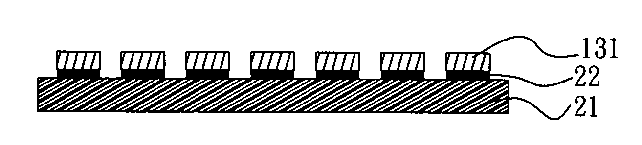
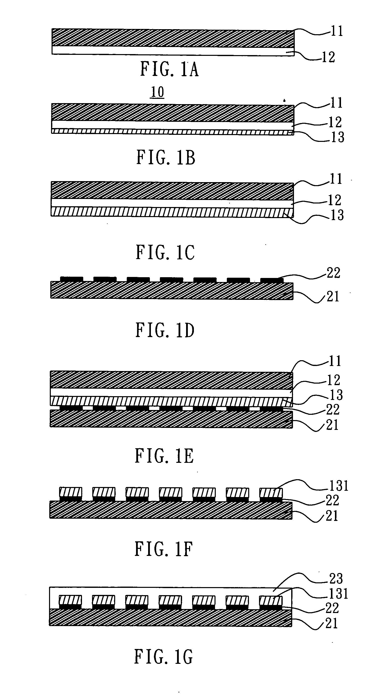
[0016] Please refer to FIGS. 1A to 1G. FIGS. 1A to 1G are schematic views show a manufacturing method for a printing circuit of a preferred embodiment according to the present invention. It comprises the following steps: [0017] (1) spreading a release layer 12 with an effect of release on a plastic film 11, as FIG. 11A shows, thereafter, electroplating a metal layer 13 on a surface of the release layer 12 by utilizing a vacuum film-electroplating technology to form a mother film 10, as FIG. 1B shows; [0018] (2) electroplating a metal layer 13, increasing the thickness of the metal layer 13, as FIG. 1C; [0019] (3) utilizing an adhesive as a printing material to print a line with a predetermined pattern on a carrier 21 on which a printing circuit is to be fabricated, by printing the adhesive onto the carrier 21 to form an adhesive layer 22; the adhesive layer 22 forms a shape of the line with a predetermined pattern, as FIG. 1D shows; [0020] (4) covering the metal layer 13 of the moth...


PUM

PropertyMeasurementUnit
Thicknessaaaaaaaaaa
Flexibilityaaaaaaaaaa
Frequencyaaaaaaaaaa

Abstract

A manufacturing method for a printing circuit uses an adhesive as a printing material to print a line pattern of a printing circuit on a carrier by means of printing, and then cause an adhesive to stick with a mother film with a release type metal to allow a part of the carrier with the adhesive to pull and attach itself with a metal film, and another part without the adhesive does not pull and attach itself with the metal film such that a metal line is formed on the carrier. The manufacturing method can simplify the manufacturing process of the printing circuit, the line fabrication is very fast, the production efficiency can be enhanced and the production cost is low.

Description

BACKGROUND OF THE INVENTION [0001] 1. Field of the Invention [0002] The present invention relates to a manufacturing method for a printing circuit, and more particularly to a manufacturing method for a line in a printing circuit such as a line of an induction current for a radio frequency identification (RFID) and a line of a flexible printed circuit board (FPC). [0003] 2. Description of Related Art [0004] One type of a general induction circuit for RFID is formed by winding a copper wire into a coil; the deficit thereof is that the outlook thereof must be manufactured to be cylinder-typed. Accordingly, the variation thereof is few, and the product cost is rather high comparing to other manufacturing processes. Another type thereof is formed by an etching method to stick; the manufacturing manner thereof is to electroplate a layer of metal on a plastic film, and after a mask is printed on a part of the surface of the metal film on which a line is desired to maintain, a unnecessary p...

Claims


Application Information

Patent Timeline
IPC IPC(8): B44C1/17
CPCH05K3/046Y10T156/19H05K2203/0528H05K2203/0522
Inventor KU, TOM
Owner K LASER TECH
Why Eureka
Try Eureka