Signal processing apparatus, signal processing method and storage system

a signal processing and signal processing technology, applied in the direction of digital signal error detection/correction, dc level restoring means or bias distortion correction, instruments, etc., can solve the problem of snr deterioration, higher decoding error rate, and more subject to snr deterioration, so as to achieve efficient correction of baseline wander

Inactive Publication Date: 2007-05-10
ROHM CO LTD
View PDF6 Cites 10 Cited by
  • Summary
  • Abstract
  • Description
  • Claims
  • Application Information

AI Technical Summary

Benefits of technology

[0015] The present invention has been made in view of the foregoing circumstances and a general purpose thereof is to provide a storage apparatus capable of correcting baseline wander efficiently, particularly for storage apparatuses required of making high-speed access.

Problems solved by technology

If such variation in the baseline of reproduced signals occurs, a problem of higher decoding error rate will arise when the recorded data are decoded from the reproduced signals.
However, simply widening the passband will lead to an SNR deterioration of reproduced signals because it cannot cut off the low-frequency noise components.
Moreover, the read amplifier, in particular, is normally sensitive to the low-frequency noise, such as 1 / f noise, so that it is even more subject to the SNR deterioration.
Hence, with a perpendicular magnetic recording system, simply lowering the low-frequency cutoff frequency of the read channel will rather result in raising the error rate.
Conventionally, baseline correction has been done by calculating the necessary amount of correction and feeding it back to a preceding stage, which results in a delay in the timing of correction as much as the time taken to calculate the amount of correction.
And this delay can be fatal and unacceptable to storage apparatuses of recent years which must make access for read and write at a speed exceeding 1 G bps.
In other words, a baseline correction, when done by the conventional method, can be inaccurate because the amount of correction to be used in the correction is based on past data.
The problem therefore is that where access at higher speed is required, this baseline wander can adversely affect the subsequent circuits for error correction and the like.

Method used


Image

  • Signal processing apparatus, signal processing method and storage system
  • Signal processing apparatus, signal processing method and storage system
  • Signal processing apparatus, signal processing method and storage system

Examples


first embodiment

[0070] Before explaining a first embodiment of the present invention in concrete terms, a brief description will be given of a storage apparatus relating to the present embodiment. A storage apparatus according to the present embodiment includes a hard disk controller, a magnetic disk apparatus, and a read / write channel, which includes a read channel and a write channel. At the read channel, correction of the above-mentioned baseline wander is made on the data read out from the magnetic disk apparatus by a feedforward control. By this arrangement, it is possible to correct baseline wander efficiently without the effects of delay occurring at the time of correction even when there is instantaneously a large wandering of baseline. This will be described in detail later.

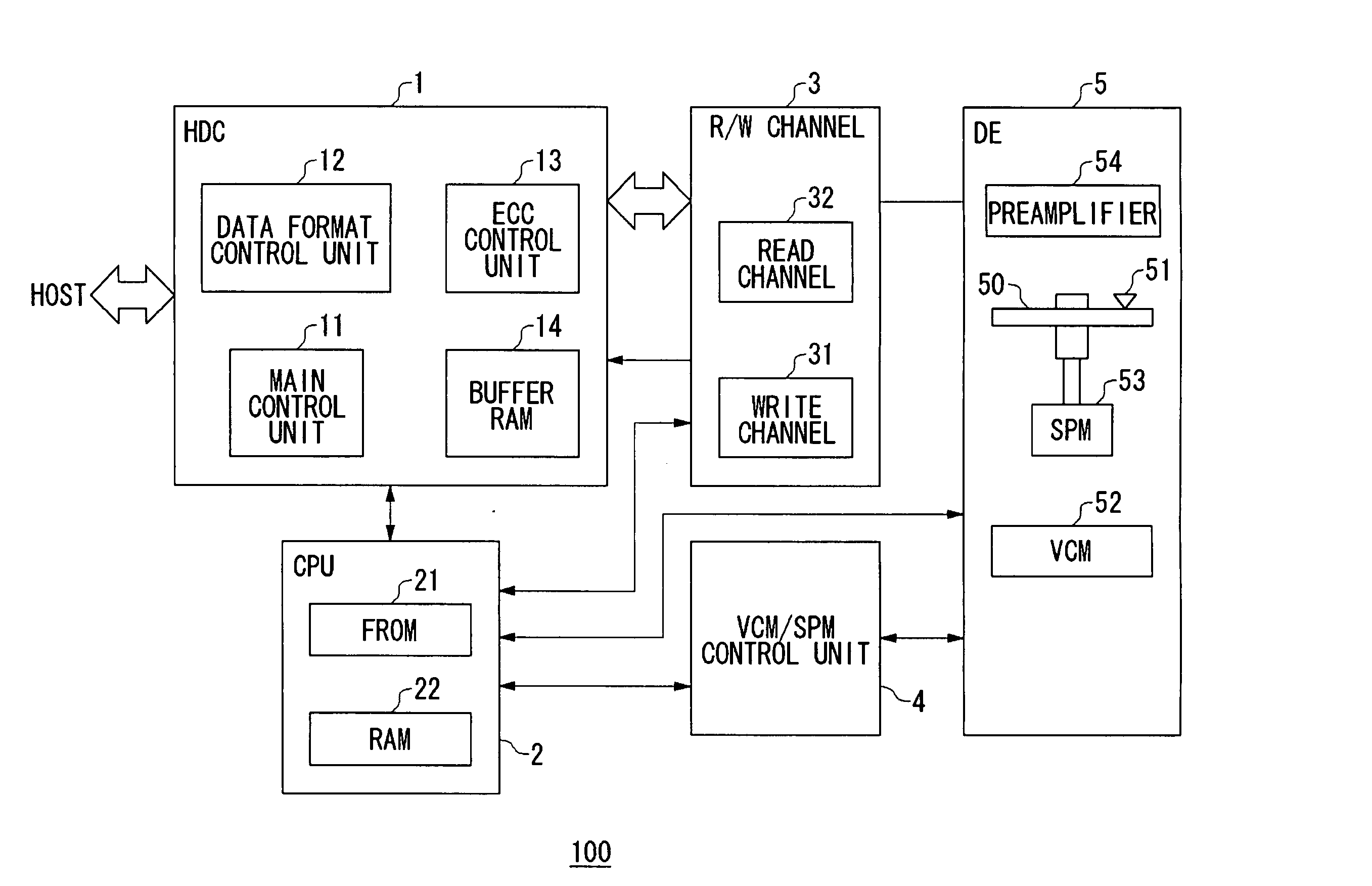
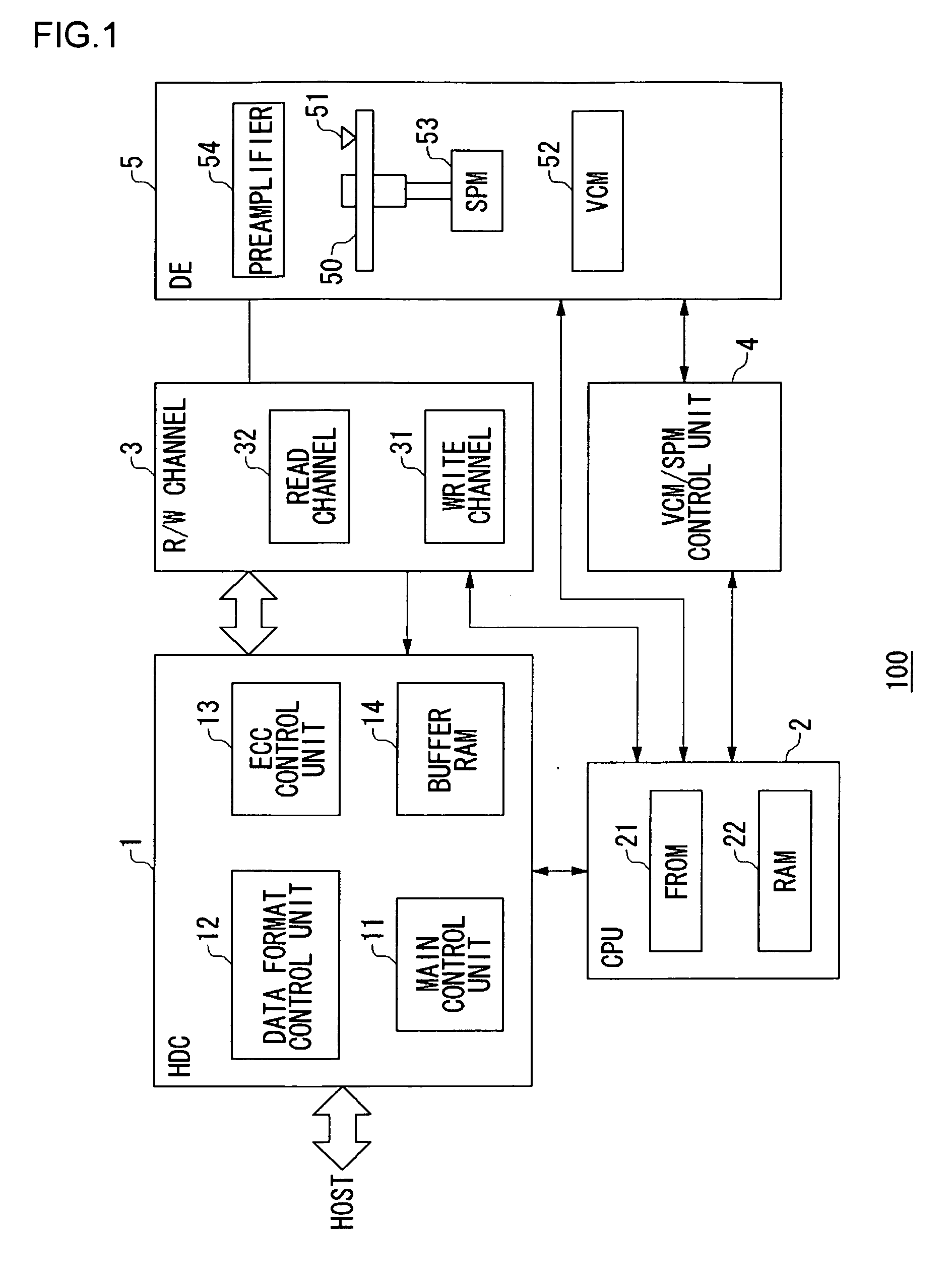
[0071]FIG. 1 illustrates a structure of a magnetic disk apparatus 100 according to a first embodiment of the present invention. The magnetic disk apparatus 100 in FIG. 1 is comprised roughly of a hard disk controller 1...

second embodiment

[0104] Before explaining a second embodiment of the present invention in concrete terms, a brief description will be given of a storage apparatus relating to the present embodiment. A storage apparatus according to the present embodiment includes a hard disk controller, a magnetic disk apparatus, and a read / write channel, which includes a read channel and a write channel. At the read channel, correction of the above-mentioned baseline wander is made on the data read out from the magnetic disk apparatus by a feedforward control, and the baseline wander is also corrected by a feedback control at a stage posterior to an A-D converter. By employing this structure, it is possible to correct baseline wander efficiently and accurately without the effects of delay occurring at the time of correction not only when there is a large instantaneous wander of baseline but also when the baseline varies gradually over a long period of time. This will be described in detail later.

[0105]FIG. 8 illus...

third embodiment

[0114] Before explaining a third embodiment of the present invention in concrete terms, a brief description will be given of a storage apparatus relating to the present embodiment. A storage apparatus according to the present embodiment includes a hard disk controller, a magnetic disk apparatus, and a read / write channel, which includes a read channel and a write channel. At the read channel, correction of the above-mentioned baseline wander is made on the data read out from the magnetic disk apparatus by a feedforward control, and the baseline wander is also corrected at stages anterior to and posterior to an A-D converter. By employing this structure, it is possible to correct baseline wander efficiently and accurately without the effects of delay occurring at the time of correction not only when there is instantaneously a large wander of baseline but also when the baseline varies gradually over a long period of time. Furthermore, the correction is made for a long-term wander at tw...


PUM

PropertyMeasurementUnit
run lengthaaaaaaaaaa
densityaaaaaaaaaa
soft-aaaaaaaaaa

Abstract

A signal processing apparatus has a plurality of baseline wander correcting units, provided in a processing path in which a predetermined processing is performed on an input signal. Baseline wander of the signal is corrected sequentially by each of the plurality of baseline wander correcting units. At least a baseline wander correcting unit placed in the initial stage may correct baseline wander by a feedback control. The baseline wander correcting units correct the baseline wanders, respectively, so that the wander of baseline can be efficiently corrected.

Description

BACKGROUND OF THE INVENTION [0001] 1. Field of the Invention [0002] The present invention relates to an access technology for a storage medium and, more particularly, to a signal processing apparatus, a signal processing method, and a storage system. [0003] 2. Description of the Related Art [0004] In the area of disk drives, attention has recently been focused on disk storage apparatuses of perpendicular magnetic recording system which are capable of increasing the recording density. With the conventional disk drives of longitudinal magnetic recording method, a magnetization corresponding to binary recorded data is formed in the longitudinal direction of the disk medium. In contrast to this, with the disk drives of perpendicular magnetic recording method, the same magnetization is formed in the depth direction of the disk medium. [0005] Generally, with disk drives, data are recorded on the disk medium by a NRZ (non-return-to-zero) record encoding method. When the recorded data are r...

Claims


Application Information

Patent Timeline
Patent Type & Authority Applications(United States)
IPC IPC(8): G11B20/10
CPCG11B20/10G11B20/10009G11B20/18
Inventor ESUMI, ATUSHILI, KAIMIZUNO, HIDEMICHI
Owner ROHM CO LTD
Why Eureka
Try Eureka