Carious tooth detection device

a carious tooth and detection device technology, applied in the field of non-destructive detection of dental caries, can solve the problems of lowering detection sensitivity, difficult to accurately identify the presence/absence of primary dental caries using the device, and difficult to detect primary dental caries, etc., to achieve the effect of high sensitivity, easy to check the degree of recovery, and easy to appreciate the importance and effect of dental caries prevention treatmen

Inactive Publication Date: 2007-05-10
KAO CORP
View PDF6 Cites 21 Cited by
  • Summary
  • Abstract
  • Description
  • Claims
  • Application Information

AI Technical Summary

Benefits of technology

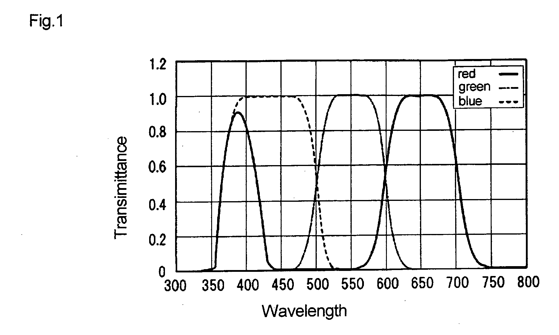
[0009] The inventors have also found that when the intensity of ultraviolet irradiation is reduced, fluorescence corresponding to blue and red is lowered for dental caries, while for a healthy tooth, the fluorescence corresponding to blue is weaker but fluorescence corresponding to red is stronger.
[0011] The use of the detecting device according to the invention allows primary dental caries to be detected with high sensitivity, so that non-surgical treatment of primary dental caries without cutting the affected area can be carried out more easily. The dental caries detecting device according to the invention can measure the degree of progress of dental caries. The process of treatment of the primary dental caries can be observed, and the degree of recovery can be checked. Therefore, the progress of the dental caries or its recovery can specifically be pointed out to the patient. The importance and effects of dental caries prevention treatment can be appreciated, which can contribute to maintenance and improvement of oral health.
[0012] The dental caries detecting device according to the invention measures the surface of a tooth, so that dental caries can be detected more precisely, and areas between teeth that are difficult to measure can be measured (measured in one location), or a healthy area and a dental caries area of a tooth can be compared and measured (measured in two locations). The fluorescence data is analyzed based on fluorescence intensities in at least two wavelength bands in the visible light range, so that dental caries (primary dental caries in particular) and its degree of progress can accurately be detected with high sensitivity.
[0013] Furthermore, using the dental caries detecting device according to the invention, a wavelength band showing different changes between a dental caries area and a healthy tooth area can be selected in fluorescence data from a tooth that changes according to change in the intensity of ultraviolet irradiation, so that analysis can be carried out based on a plurality of fluorescence intensities in the wavelength band. In this way, the presence of dental caries (primary dental caries in particular) and its progress degree can accurately be detected with high sensitivity.

Problems solved by technology

It is often the case with primary dental caries in particular that no such bacteria in an oral composition are detected in affected locations, and therefore it is difficult to detect primary dental caries using the device disclosed by Patent Document 1.
More specifically, the analysis result according to the fluorescence information depends on the presence / absence of oral bacteria, and therefore it is difficult to accurately identify the presence / absence of primary dental caries using the device.
The device according to Technical Document 4 is however directed to measuring only red fluorescence whose intensity is low, which is not sufficient for detecting the presence / absence of dental caries and is liable to the effect of the measurement environment such as the effect of external light.
This lowers the detection sensitivity.

Method used


Image

  • Carious tooth detection device
  • Carious tooth detection device
  • Carious tooth detection device

Examples


example 1

[0122] In Example 1, according to the “measuring method using data obtained from a single location” in the dental caries detecting method according to the embodiment, the dental caries degree CD1 was calculated for the measuring areas L1, M1, H1, L1′, M1′, and H1′ of the light intensity U1, and the correlation coefficients between the dental caries degree CD1 and the mineral decreasing ratio were obtained.

example 2

[0126] In Example 2, according to the “comparison measuring method” among the dental caries detecting methods according to the embodiment, the dental caries degree CD2 was calculated for the measuring areas (L1, L1′), (M1, M1′), and (H1, H1′) of the light intensity U1 and the correlation coefficients between the calculated dental caries degrees CD2 and the mineral decreasing ratios were obtained.

example 3

[0130] In Example 3, according to the “light intensity change measuring method” among the dental caries detecting methods according to the embodiment, luminance changes (R1−R2), (G1−G2), and (B1−B2) and the dental caries degrees CD3 and CD4 were calculated for the measuring areas L2,1, M2,1, H2,1, L2,1′, M2,1′, and H2,1′ of the light intensities U1 and U2, and the correlation coefficients between the dental caries degrees CD3 and CD4 and the mineral decreasing ratios were obtained. The results of measuring according to Example 3 are given in Tables 6 and 7.

TABLE 6luminance change (340-94)mineralmeasuringdecreasingarearatio (%)R1-R2G1-G2B1-B2L2,1Dental caries11.214851527727821area(minor)M2,1Dental caries25.626071728330921area(moderate)H2,1Dental caries68.91046893116596area(severe)L2,1′Healthy area0−4432295530068M2,1′Healthy area0−26901932631399H2,1′Healthy area0−25142448523426correlation coefficient0.557−0.890−0.739with mineraldecreasing ratio

[0131]

TABLE 7Example 3(intensity change...


PUM


Abstract

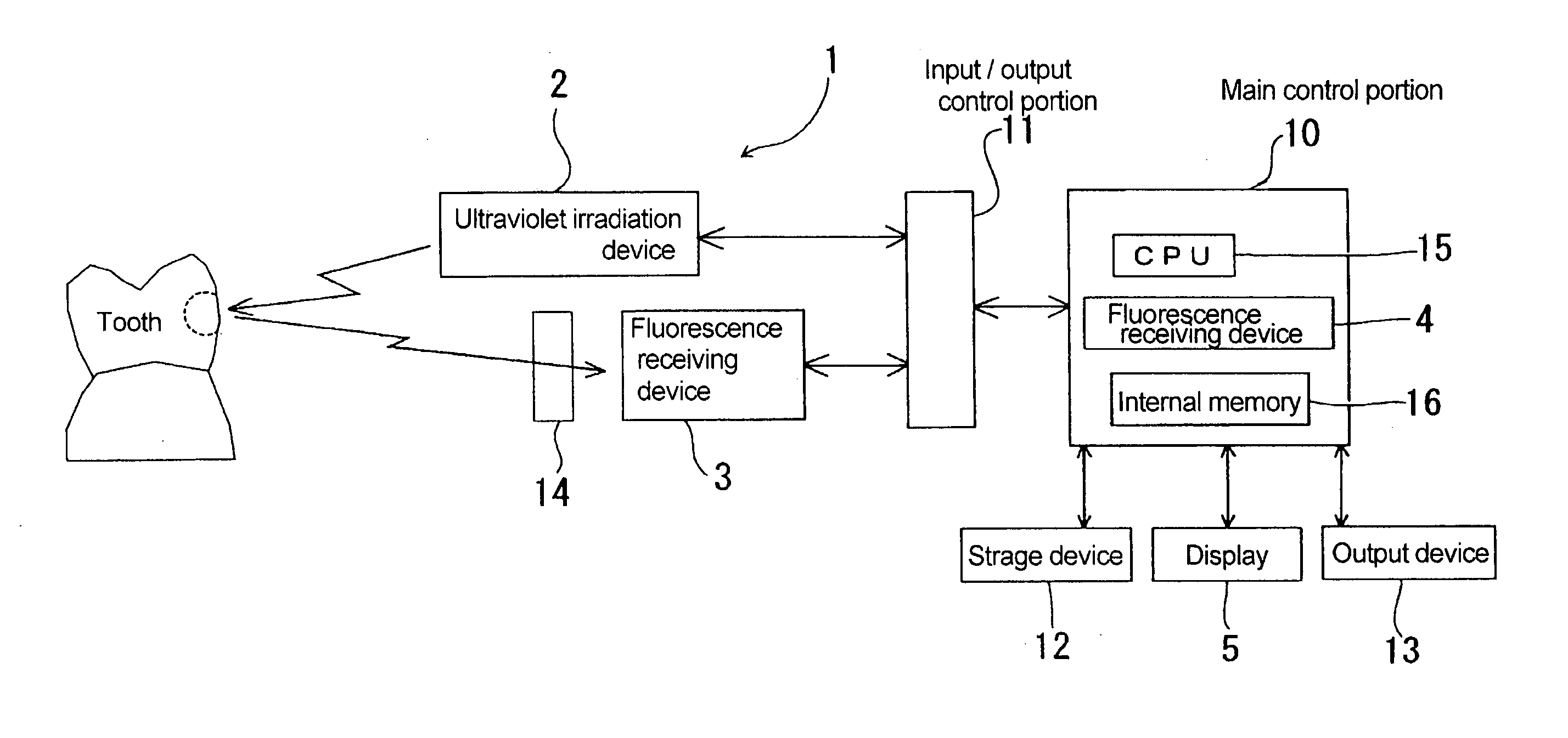
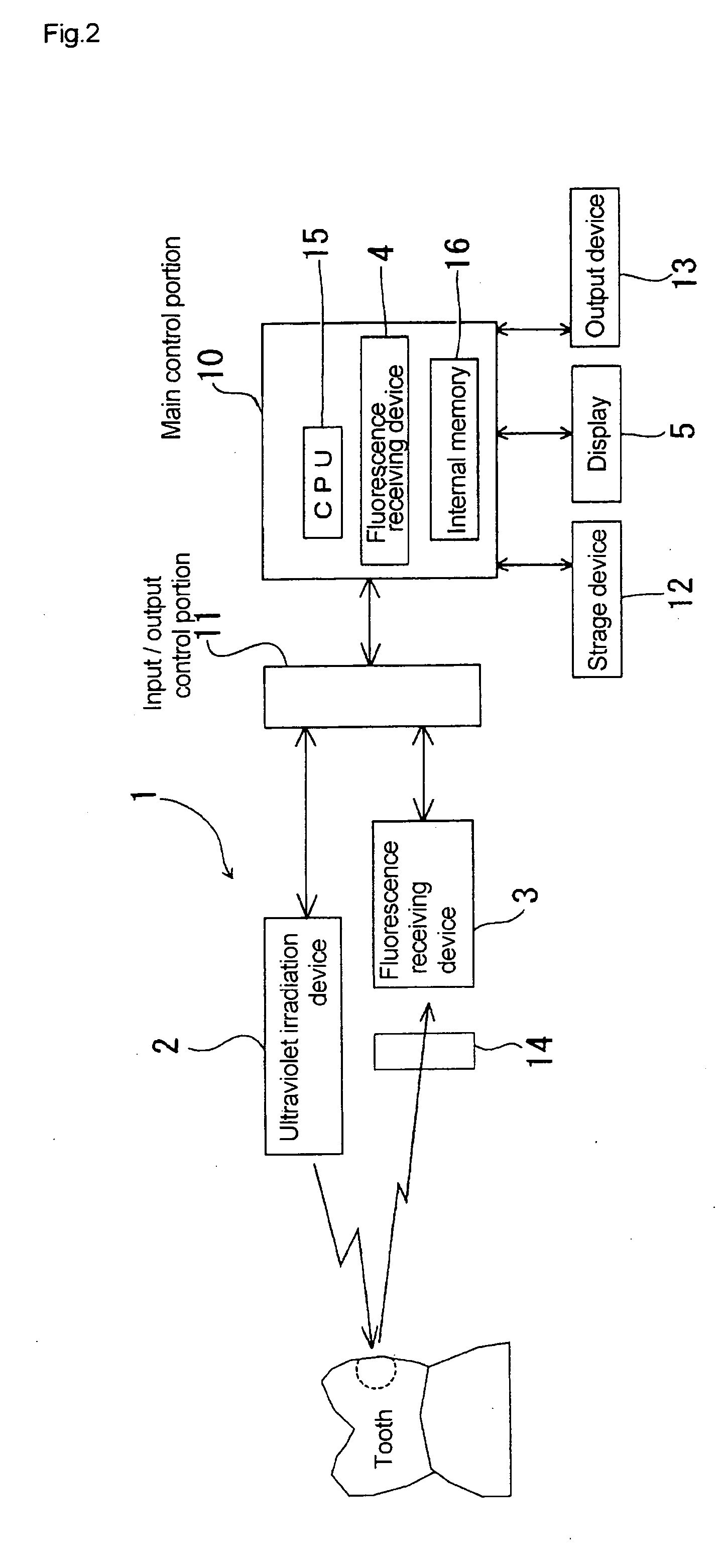
A dental caries detecting system 1 according to the invention includes an ultraviolet irradiation device 2, a fluorescence receiving device 3 that receives fluorescence from a tooth based on ultraviolet irradiation from the ultraviolet irradiation device 2, a fluorescence data analysis portion 4 that analyzes fluorescence data transmitted from the fluorescence receiving device 3, and a display 5 that displays analysis data analyzed by the fluorescence data analysis portion 4. The fluorescence data analysis portion 4 is adapted to analyze said fluorescence data based on the fluorescence intensities in at least two wavelength bands in a visible light range.

Description

TECHNICAL FIELD [0001] The present invention relates to a technique of detecting dental caries, and more particularly, to a technique of non-destructively detecting dental caries in early stages based on fluorescence information from teeth. BACKGROUND ART [0002] Technical Document 1 (Japanese Patent Laid-Open Publication No. 2001-299699) discloses a conventional technique of detecting dental caries using light. The disclosed device irradiates a tooth with red light (600 nm to 670 nm) as excitation light and measures only the intensity of fluorescence from the tooth received by a photodiode. The device detects dental caries using fluorescence emitted from oral bacteria, and therefore dental caries can be detected when it progresses so far as to form a cavity in the tooth, and bacteria proliferation is in progress inside the cavity. [0003] However, the degree of progress of primary dental caries is not strictly related to the presence and number of bacteria. It is often the case with ...

Claims


Application Information

Patent Timeline
Patent Type & Authority Applications(United States)
IPC IPC(8): A61C5/00A61C1/00A61B5/00
CPCA61B5/0088
Inventor YAMAGISHI, ATSUSHI
Owner KAO CORP
Why Eureka
Try Eureka