Light-emitting form exhibiting an aura

Inactive Publication Date: 2007-05-17
ZARIAN JAMES R
View PDF42 Cites 9 Cited by
  • Summary
  • Abstract
  • Description
  • Claims
  • Application Information

AI Technical Summary

Benefits of technology

[0057] Another advantage of the present invention is realized in the cost of materials and cost of production. Known light guides, as disclosed in U.S. Pat. Nos. 4,261,936, 5,111,526, 5,052,778, 4,957,347, 5,406,641 and 5,485,541, function similarly, although not as efficiently, compared to the light-emitting form in accordance with the present invention; however, the cost of raw materials is much higher. Additionally, the cost of manufacturing is much higher due to the capital costs and labor associated with the processes. The advantage of the present invention is particularly more pronounced for light-emitting media with high volumes (e.g, mass volume), such as a container with a diameter of 5 mm and larger.
[0058] As an important aspect of the invention the core of the light-emitting medium may be a liquid, oligomer (telomer), prepolymer, polymer, copolymer and/or combinations thereof, or mixtures of oligomers and/or polymers in a solution.
[0059] Various liquids are contemplated for use as the core with the present invention. Exemplary liquids suitable for the present invention include oils such as, mineral oils, fluorinated oils, silicone oils; or liquids in the form of salt solutions, such as aqueous solution of inorganic salts (i.e. sodium chloride or

Problems solved by technology

The manufacturing processes for the production of this class of light guides is rather specialized and cost-prohibitive for many applications.
'719 discloses the following ways of providing side-scattering capability: “Scoring the surface of the cylindrical core with angular cuts or discontinuities.” However this is an expensive and inconsistent method.
“Introducing bubbles or foreign materials into the cylindrical core material while the cylindrical core is still molten.” The molten state is not well defined, and like similar art, the bubbles and foreign materials contribute to non-uniform and excessive absorption of light.
“Forming the tubular cladding from a material which has an index of refraction exceeding that of the cylindrical core.” This method is not well defined and the preferred cladding material, polychlorinated poly phenyl, does not readily form into a tubular clad

Method used


Image

  • Light-emitting form exhibiting an aura
  • Light-emitting form exhibiting an aura
  • Light-emitting form exhibiting an aura

Examples


example 1

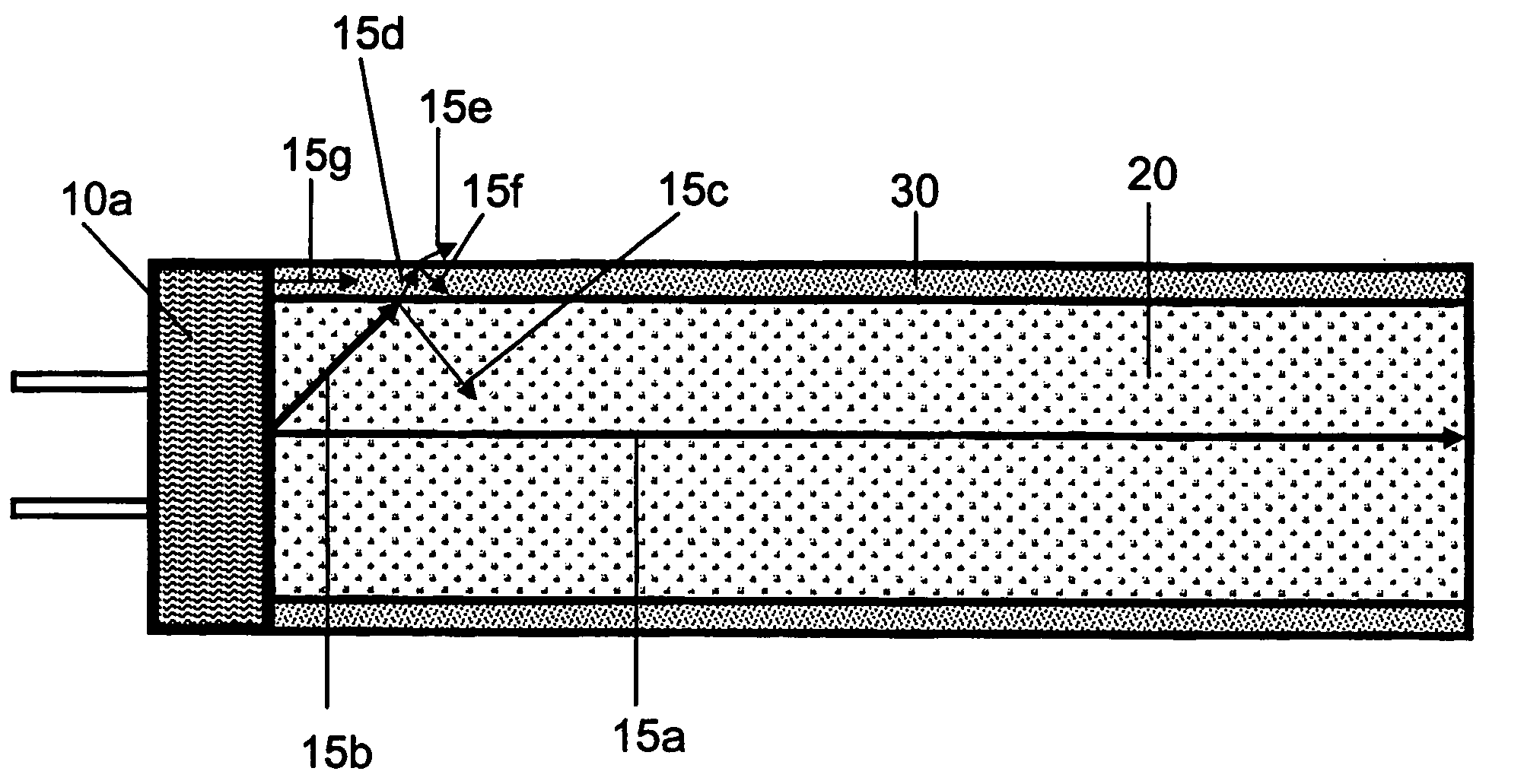
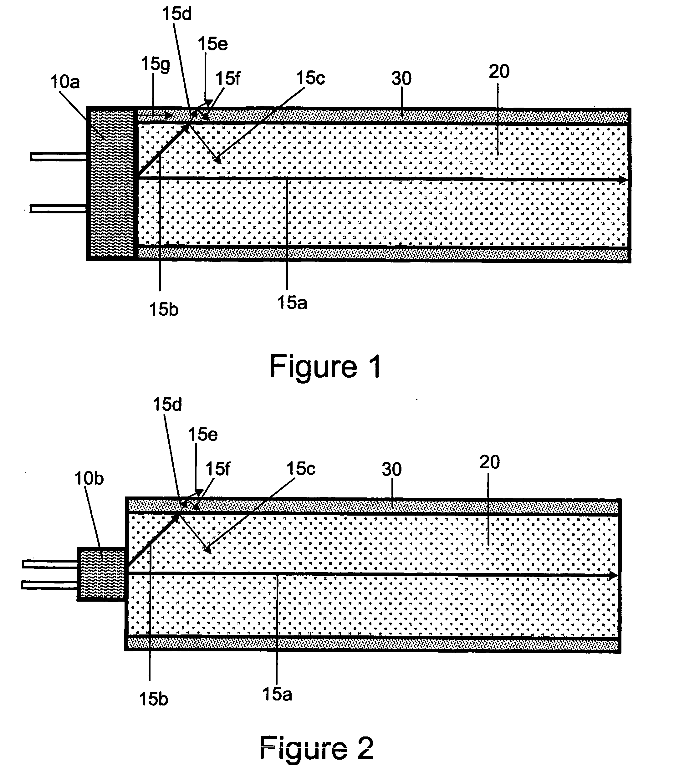
[0110] An ether-based polyurethane tubing, 100 cm in length, with 6.5 mm inside diameter and 8.0 mm outside diameter was filled with a very viscous, water clear, purified oil supplied by STE Oil Company of San Marcos, Tex. One Agilent LED (HLMT-PG00), San Jose, Calif. was inserted at each end of the tube. LEDs were immersed and were in direct contact with the oil. When LEDs were lit, the light-emitting device glowed uniformly along its entire length and had an aura very similar to neon, although not as bright. The polyurethane tubing's refractive index was reported at 1.54 and the oil's refractive index was lower.

example 2

[0111] Example 1 was repeated with a longer length tubing (e.g. 200 cm). The device as expected did not exhibit a uniform glow throughout the entire length of the device and was not as bright as Example 1.

example 3

[0112] To overcome the shortcoming of Example 2, Example 2 was repeated except Omron red 2MDR01-85R1A LEDs, Schaumburg, Ill., with higher intensity and a narrower viewing angle as compared to Agilent LED (HLMT-PG00) were used. The light-emitting device glowed uniformly along its entire length and had an aura very similar to neon, although not as bright.


PUM

PropertyMeasurementUnit
Lengthaaaaaaaaaa
Lengthaaaaaaaaaa
Fractionaaaaaaaaaa

Abstract

A light-emitting form comprises an elongated light guide illuminated by a light source (10a) such as an LED that sheds light into the end of the light guide. The light guide comprises a tubular light-transmitting container (30) consisting essentially of a substantially amorphous polymer, and an elongated light-transmitting core (20), which may be liquid, with an index of refraction lower than the index of refraction of the container. The light guide exhibits an aura, wherein the outside surface of the container (30) illuminates its surroundings and appears to glow, rather like neon lighting tubes.

Description

TECHNICAL FIELD [0001] The present invention broadly relates to a light-emitting form for transmitting and emitting light at one or more wavelengths. More specifically, the light-emitting form is elongated and can be tubular (cylindrical) simulating a linear light guide. BACKGROUND ART [0002] Various lighting systems are known using light-emitting diodes (LEDs). LEDs have been the center of focus because of aesthetic, design flexibility, color changing, long life, small physical dimensions and other attributes that together advantageously serve the intended markets. LEDs as a source of light offer many advantages; moreover, their usefulness is enhanced by the use of optical elements, such as light guides, lenses, refractors, reflectors to disperse, reflect and refract light. As such, LEDs have been combined with various light conduits, such as so called “optical fibers”, “fiber optics”, “light pipes” and “light guides”, collectively categorized as light guides. These lighting system...

Claims


Application Information

Patent Timeline
IPC IPC(8): G02B6/02G02B6/032B29C35/06F21K99/00H01L
CPCF21K9/00G02B6/001G02B6/02033G02B6/032F21K9/17F21Y2103/003F21K9/27F21K9/61F21Y2103/10F21Y2115/10
Inventor ZARIAN, JAMES R.
Owner ZARIAN JAMES R
Why Eureka
Try Eureka