Light measurement apparatus and light measurement method

a light measurement and light measurement technology, applied in the field of light measurement apparatus and light measurement method, can solve the problems of limited measurable wavelength range and difficult to measure phase variation, and achieve the effect of improving measurement accuracy

Inactive Publication Date: 2007-05-17
YOKOGAWA ELECTRIC CORP
View PDF9 Cites 6 Cited by
  • Summary
  • Abstract
  • Description
  • Claims
  • Application Information

AI Technical Summary

Benefits of technology

[0035] Measuring the intensity of the light to be measured or the reference standard light independently (of amplitude

Problems solved by technology

Consequently, a measurable wavelength range is limited in the conventional measurement technique depending on the local light.
Moreover, although the intensity variation (a

Method used


Image

  • Light measurement apparatus and light measurement method
  • Light measurement apparatus and light measurement method
  • Light measurement apparatus and light measurement method

Examples


first embodiment

[0069] The first embodiment of the present invention will be described with reference to FIGS. 1-16.

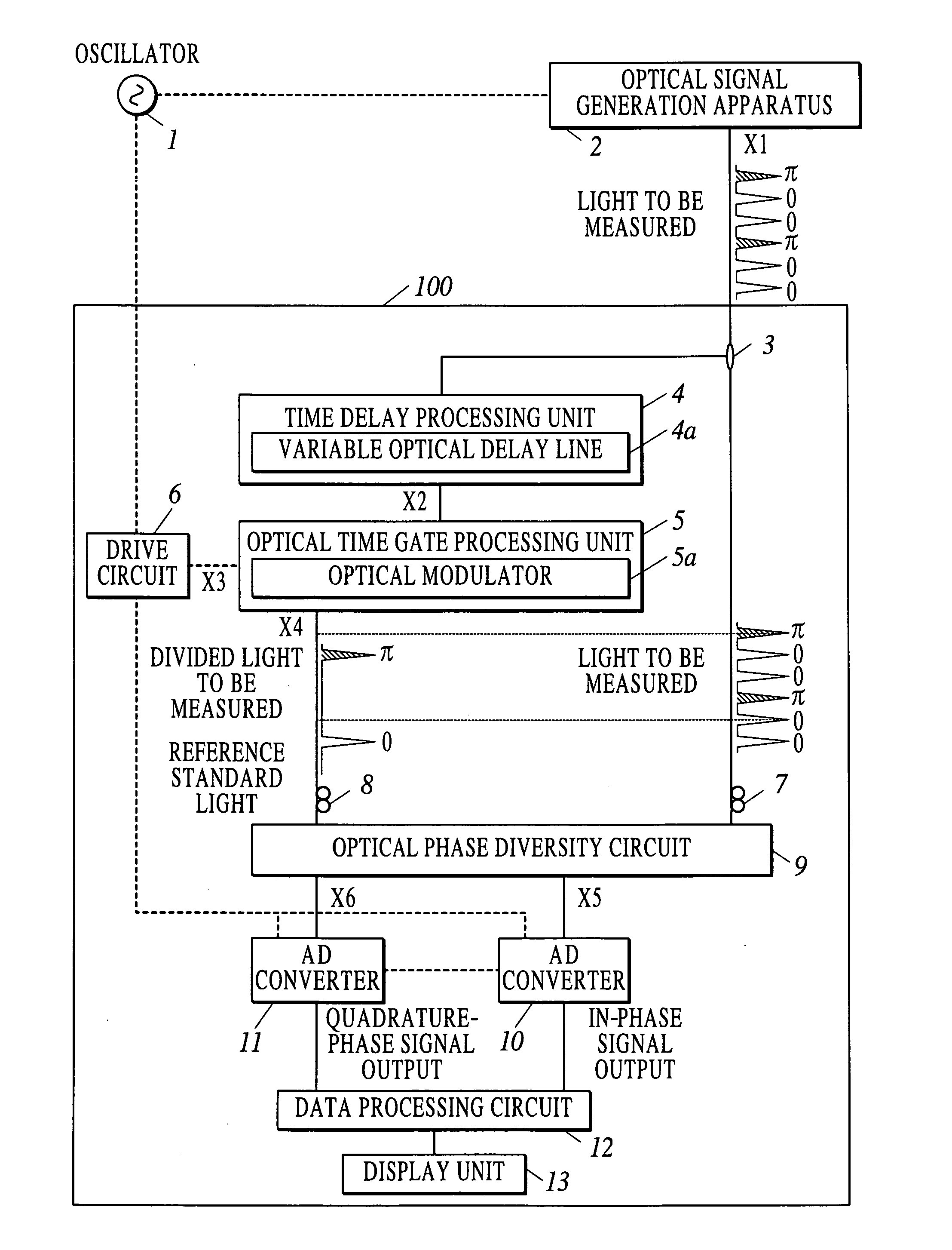
[0070]FIG. 1 shows an example of the internal configuration of a light measurement apparatus 100 according to the first embodiment, an oscillator 1 and an optical signal generation apparatus 2.

[0071] The oscillator 1 outputs an electric clock signal synchronized with the light to be measured that is generated by the optical signal generation apparatus 2 to the optical signal generation apparatus 2 and a drive circuit 6 of the light measurement apparatus 100.

[0072] The optical signal generation apparatus 2 supposes an optical signal on which data propagating through an actual transmission path is superimposed, and generates the light to be measured on which random data is superimposed in synchronization with the electric clock signal input from the oscillator 1. As the light to be measured on which the random data is superimposed, for example, an optical signal that is modulated by ...

first modified example

[0104] Although the case where the time delaying processing and the optical time gate processing are performed to one piece of the light to be measured branched by the optical branching device 3 has been shown in the light measurement apparatus 100 of FIG. 1, a time delay may be given to one piece of the light to be measured branched by the optical branching device 3 by a time delay processing unit 14 including a variable optical delay line 14a, and the optical time gate processing may be performed to the other piece of the branched light to be measured by an optical time gate processing unit 15 including an optical modulator 15a, as shown in a light measurement apparatus 101 of FIG. 8.

second modified example

[0105] An optical time gate processing unit 16 of a light measurement apparatus 102 shown in FIG. 9 performs the optical time gate processing by a mode-locked laser 16a. The mode-locked laser 16a uses a light injection locking technique using the light to be measured as a trigger of laser oscillation. Because the laser light obtained by the light injection locking is in the same phase state as the phase of the light to be measured, which is the trigger, the laser light can be used as the reference standard light.


PUM


Abstract

Disclosed is a light measurement apparatus including: an optical branching device to branch light to be measured into a plurality of pieces; a time delay processing unit to give a predetermined time delay to one branched piece of the light; an optical phase diversity circuit to output an in-phase signal component and a quadrature-phase signal component of the light to be measured by interference of the light to be measured and a reference standard light whose relative time difference is a time given by the time delay, wherein the reference standard light is another branched piece of the light or the one branched piece of the light having been subjected the time delay; and a data processing circuit to calculate at least one of an amplitude variation and a phase variation of the light to be measured based on the in-phase signal component and the quadrature-phase signal component.

Description

BACKGROUND OF THE INVENTION [0001] 1. Field of the Invention [0002] The present invention relates to a light measurement apparatus and a light measurement method which measure at least one of the amplitude and the phase of an optical signal. [0003] 2. Description of Related Art [0004] In recent years, as a modulation method of a transmission signal used for optical communication, a phase modulation method which adds information to the phase of light has been proposed in addition to a conventional intensity modulation method. As a digital phase modulation method, for example, there are binary phase-shift keying (BPSK) in which phases 0 and π of the light correspond to binary digital values, differential phase-shift keying (DPSK) in which a digital value is discriminated based on a phase difference between bits adjoining each other, and the like. Moreover, multilevel modulation methods such as amplitude phase-shift keying (APSK) in which a digital value is added to both the amplitude ...

Claims


Application Information

Patent Timeline
IPC IPC(8): G03F1/00
CPCG01J9/04
Inventor TANIMURA, KAZUNORI
Owner YOKOGAWA ELECTRIC CORP
Why Eureka
Try Eureka