System and method for monitoring an analyte

a technology of analyte and system, applied in the field of system and method for monitoring analyte, can solve the problem of slow process of using a series of biochip assays

Inactive Publication Date: 2007-05-17
CALIFORNIA INST OF TECH
View PDF8 Cites 53 Cited by
  • Summary
  • Abstract
  • Description
  • Claims
  • Application Information

AI Technical Summary

Benefits of technology

[0026] Additional embodiments of the present invention provide for systems for monitoring an analyte in a sample, comprising a fluidics apparatus adapted to create a fluid stream of the sample and / or to create a series of small drops of the sample; a laser adapted to operate at a wavelength that is capable of inducing an intrinsic fluorescence of the analyte; a counting component adapted to determine the concentration of the analyte; an reporting component adapted to report the concentration of analyte that is above or below a predetermined concentration; and a sorting component adapted to apply a charge to a portion of the sample containing the analyte and to deflect the charged portion of the sample containing the analyte into a container. Based on te fluorescence detected, different analytes may be deflected into different containers. In one embodiment, the fluidics apparatus is a flow cytometer. In various embodiments, the analyte may be a microorganism or a cell.

Problems solved by technology

However, the use of a series of biochip assays can be a slow process and can necessitate many separate steps to achieve the analysis.

Method used


Image

  • System and method for monitoring an analyte
  • System and method for monitoring an analyte
  • System and method for monitoring an analyte

Examples


example 1

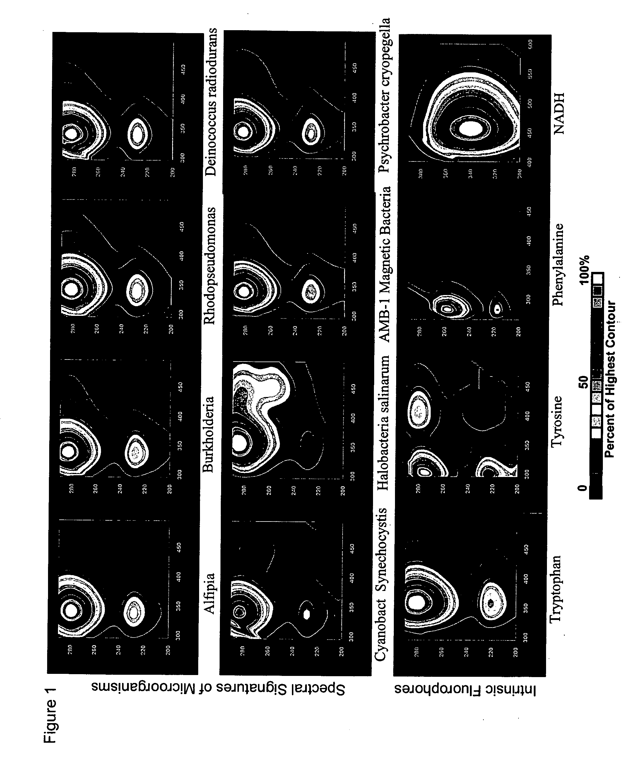
[0091]Alfipia, Burkolderia, and Rhodopseudomonas are bacterial strains that were cultured from soil obtained from the dry valley of the Atacama Desert in Chile. Halobacteria salinarum, Deinococcus radiodurans, and Psychrobacter cryopegella have adapted to conditions of high salinity, dryness & radiation, and cold temperatures, respectively. Magnetosomes (intracellular magnetite crystals) in AMB-1 cause them to be ferromagnetic. Synechocystzs sp. are photosynthetic oxygen producing cyanobacteria and in the absence of light, can survive by utilizing energy and carbon from an appropriate source (e.g. glucose). All of these microorganisms have a dominant tryptophan component in their EEM (EEM's of Synechocystis sp. and Halobacteria also show the presence of tyrosine). See FIG. 1.

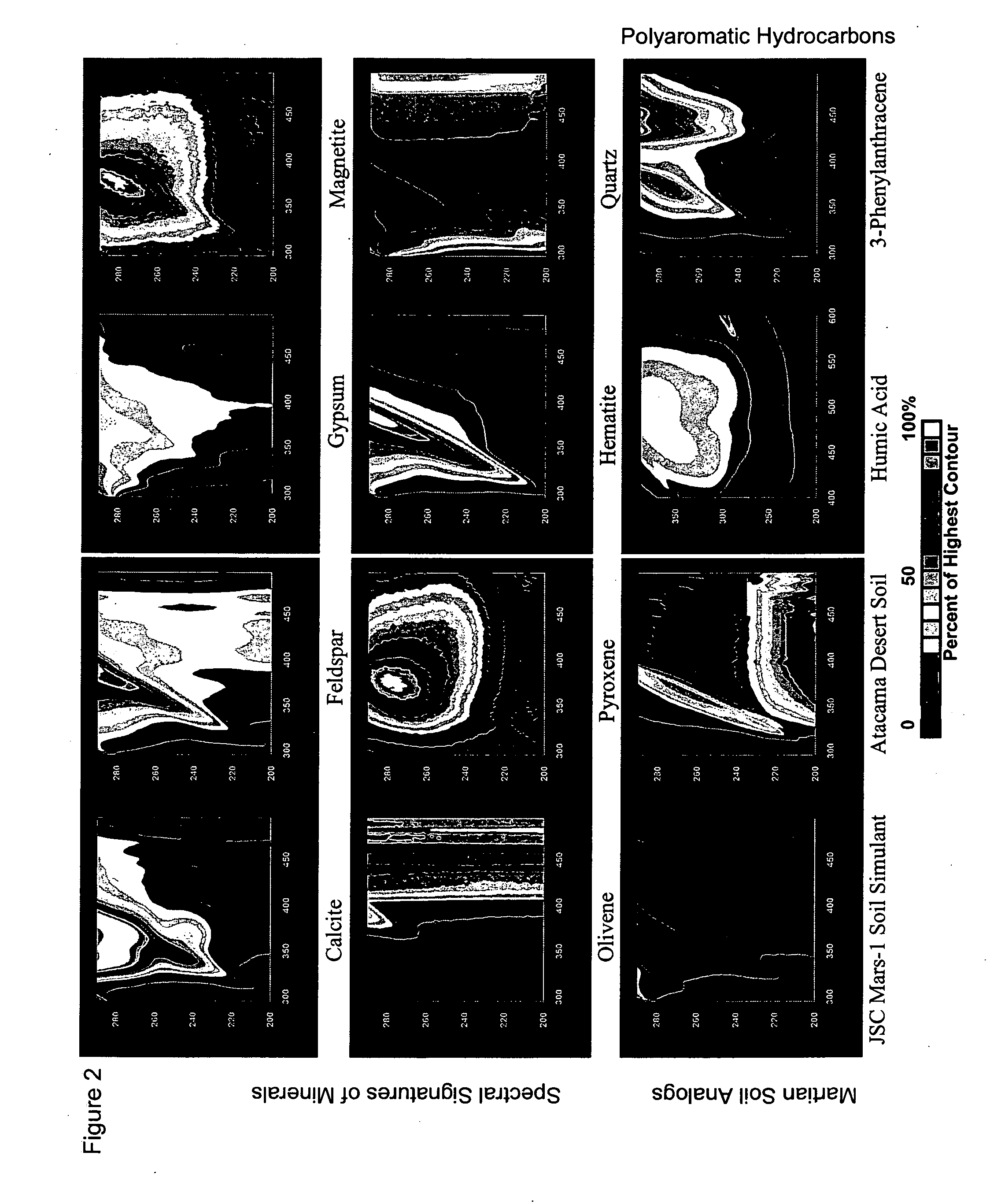
[0092] While metal ion impurities can change the appearance of EEM signatures, none of these signatures, except nominally pyroxene and magnetite (both minimally fluorescent, different peak position), are simila...

example 2

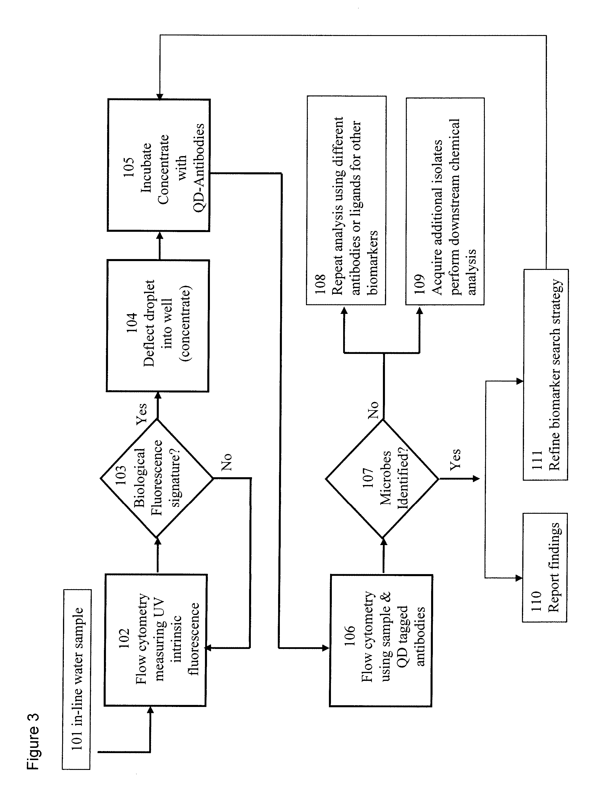
[0093] Reagentless detection. A large frame argon laser and a frequency doubled argon laser are tuned to 275 nm and 229 nm, respectively. These wavelengths are used to interrogate the hydrodynamically focused fluid stream containing the sample. Forward and side scatter data from a Krypton laser (407 nm) and intrinsic fluorescence from the bacteria (340 nm) in the stream is collected by photomultipliers and used to provide a reagentless detection of single bacteria as they flow by. Photomultipliers may also be used to measure fluorescence in the 330 nm regime using separate spots on the sample flow stream where 229 nm and 275 nm light are applied using a frequency doubled and large frame UV argon laser respectively. If a predetermined threshold is exceeded, then the bacteria are collected from the stream by electrostatically deflecting them into a test tube. Alternatively, the bacteria / second detection rate is used to determine if a predetermined threshold (e.g., a threat threshold) ...


PUM

PropertyMeasurementUnit
wavelengthaaaaaaaaaa

Abstract

The present invention provides for a monitoring system and method to monitor an analyte, including determining the presence of the analyte and analyzing the analyte; for example, cellular chorography and biological threats. The system and method use a fluidics apparatus (e.g., a flow cytometer), a computer, a probe synthesizer and/or an initial set of fluorophore conjugated probes to monitor the analyte. The fluidics apparatus is adapted to determine the presence of the analyte based on the intrinsic fluorescence of the analyte, and/or to determine the binding of the probes to the analyte in the sample. The binding information is analyzed by the computer by comparing the binding results with a database of information regarding the analyte. The information gained allows the probe synthesizer to synthesize new probes for a subsequent iteration of the process, wherein additional information regarding the analyte is gained with every iteration.

Description

[0001] This application claims priority to U.S. provisional application Ser. No. 60 / 706,960, filed Aug. 10, 2005, and U.S. provisional application Ser. No. 60 / 750,534, filed Dec. 15, 2005.GOVERNMENT RIGHTS [0002] The invention described herein was made in the performance of work under a NASA contract, and is subject to the provisions of Public Law 96-517 (35 U.S.C. §202) in which the Contractor has elected to retain title.FIELD OF INVENTION [0003] This invention relates a system and method for monitoring an analyte, including determining the presence of the analyte and / or analyzing the analyte. The system may be used to monitor and analyze a variety of analytes; for example, cellular chorography, microorganism phenology and biological threats. BACKGROUND [0004] All publications herein are incorporated by reference to the same extent as if each individual publication or patent application was specifically and individually indicated to be incorporated by reference. The following descr...

Claims


Application Information

Patent Timeline
Patent Type & Authority Applications(United States)
IPC IPC(8): C12Q1/68G01N33/53G06F19/00
CPCG01N15/1459G01N21/6428G01N2015/0088
Inventor LAMBERT, JAMES L.FISHER, ANITA M.BORCHERT, MARK S.
Owner CALIFORNIA INST OF TECH
Why Eureka
Try Eureka