Heart failure is estimated to cost the US economy today more than $40 billion annually.
Current treatment methods require hospitalization and may be extremely costly (on average, over $16,000 per patient
admittance).
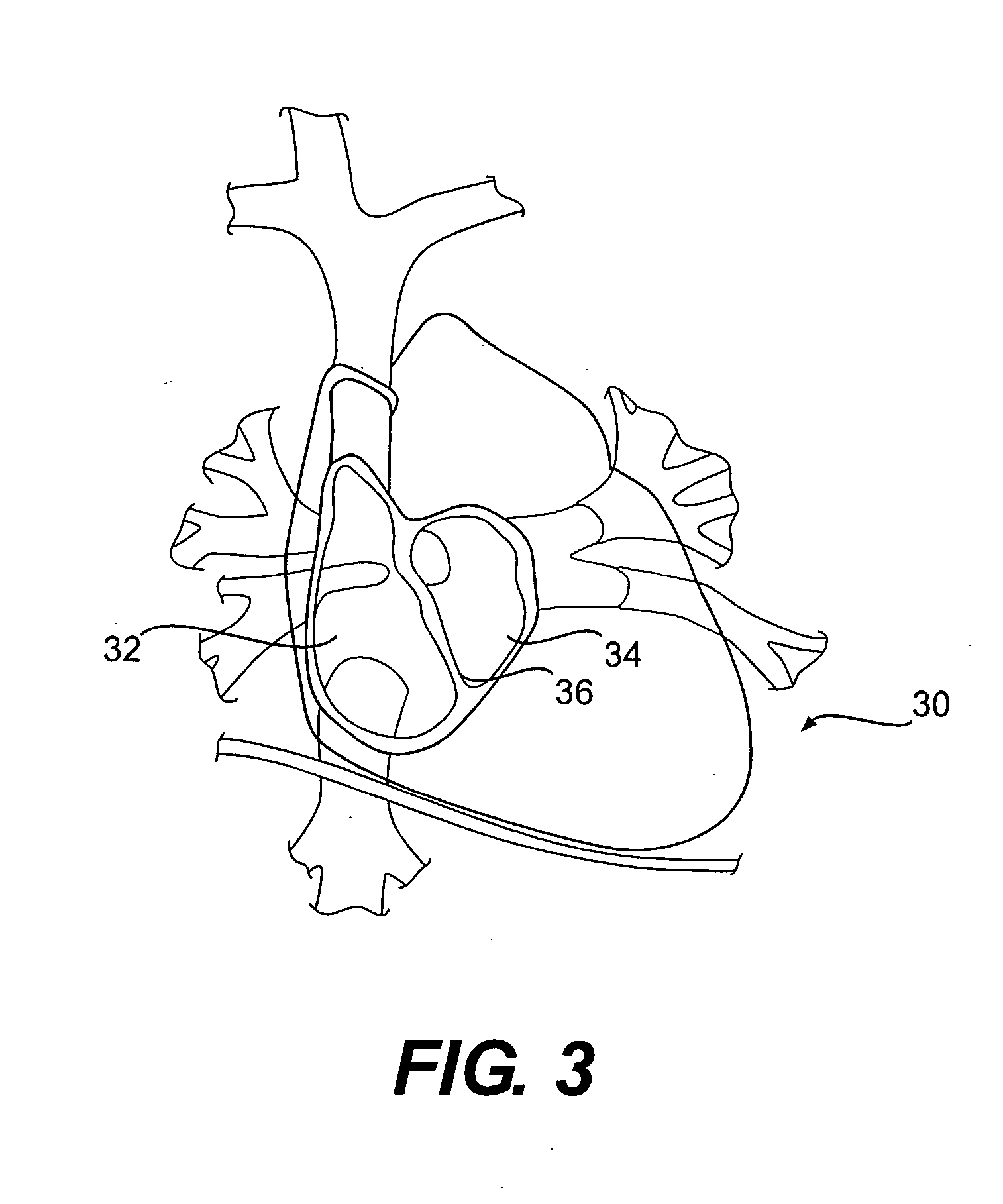
For example, the telemetric sensor described in U.S. Pat. No. 6,855,115 can be implanted in the heart by a
catheter and is not designed for surgical implantation.
However, a
disadvantage of such a configuration is its required flexibility as constant and precise acquisition of measurement data may not be possible when the sensor is placed on or close to the
cardiac muscle, and therefore is exposed to the cardiac motions, which may influence correct pressure readings.
As a consequence, the
capacitance of the
capacitor may be changed and measurement values may deteriorate and / or deviate from the true value.
Another
disadvantage of this type of sensor is due to its use of a pressure-dependent LC-oscillator.
Thus, any damage to the material can affect the pressure measurements obtained.
Further, as the sensor is influenced by the surrounding media of the sensor, a corruption of measurement values may occur.
In addition, there is no circuitry in this type of sensor to digitize the
pressure measurement values acquired.
Using analog signals may result in external interference during the acquisition and transmission of data, which causes inaccuracies in readings.
However, such a device requires a housing for the electronic
signal processing circuitry, which results in a larger and heavier sensor structure that can cause strain on the heart when implanted into a
heart wall.
Moreover, the
catheter and housing configuration creates a more complicated, mechanical structure that may be at
increased risk for
mechanical failure, and therefore is not suitable for long term implantation.
Moreover, because
digitization of the
signal does not occur until outside of the heart, there is a risk of interference in the wire connecting the sensor and the electronic
processing circuitry, as analog interference may result from external sources.
Such movement may harm connections, such as connections between wires and the
pressure sensing chip.
Thus, the use of such
pressure sensor chips is not suited for the environment of the heart, where there is cyclical and dynamic movement, and where there is continuous and turbulent fluid movement around the
pressure sensor.
Conventional techniques to provide stability and support to such known
pressure sensing chips to enable their use as a cardiovascular pressure sensors would not likely succeed.
For example, when
soldering is used for the connection, the heat may damage the chip.
However, such substrates have different coefficients of
thermal expansion than the chip.
Thus, as the temperature changes, the substrate expands and contracts at a different rate then the
pressure sensor chip, thereby causing stress and strain on the pressure sensing chip and increasing the risk of damage and / or inoperability.
Other known pressure sensors require a cable connection between the pressure sensor inside the heart and the external body monitoring device However, such a cable clearly requires an entry into the body.
An entry may be inconvenient and require the implantation of both the device and the entry, as well as increase the
risk of infection for the patient.

