Engine control unit to valve control unit interface

a technology of which is applied in the direction of electric control, braking system, instruments, etc., can solve the problems of difficult restoration of operation control of valve timing, degraded dedicated link between engine control unit and valve control unit, and rapid and accurate control of engine torqu

Inactive Publication Date: 2007-05-24
FORD GLOBAL TECH LLC
View PDF11 Cites 46 Cited by
  • Summary
  • Abstract
  • Description
  • Claims
  • Application Information

AI Technical Summary

Benefits of technology

[0002] Operation of an engine may be improved by accurately delivering a desired engine torque, such as via valve operation and / or throttle control. For example, varying the valve timing may result in rapid and accurate control of the engine torque.
[0003] In some cases, valve timing may be managed by a valve control unit (VCU). An engine control unit (ECU) may relay to the valve control unit desired / actual valve timing information. In one example, the engine control unit is linked to the valve control unit through a communication link which enables the engine control unit to provide commands to control operation of the valve control unit. The control of operation of the valve control unit enables selective management of the valve timing which may enhance operation of the engine. The engine control unit and valve control unit may be coupled through a dedicated controller area network (CAN) which enables one-on-one communication between the engine control unit and the valve control unit.
[0005] In one approach, at least some of the above disadvantages may be overcome by a method providing for backing up the dedicated communication link between the engine control unit and the valve control unit. The method comprises providing a back up system and a message system. As such, upon determination of degradation of the dedicated communication link between the engine control unit and the valve control unit, a preloaded valve timing schedule is introduced by the valve control unit. Further, a message system is activated to transmit operational status information to the engine control unit from the valve control unit. In this way, it is possible to provide continual valve control while enabling restoration of the communication link between the engine control unit and the valve control unit.
[0006] In one approach, at least some of the above disadvantages may be overcome by a method for controlling engine operation, comprising: stopping engine operation in response to degraded communication between an engine control unit and a valve control unit, where the valve control unit controls valve operation of at least one electrically actuated cylinder valve of the engine, and restarting the engine, even in the presence of the degraded communication, using a communication of cam or crank angle separate from said degraded communication. In this way, it is possible to restart an engine in the event of an engine stall or purposeful shutdown in the event of degraded communication. This may be especially advantageous on an engine having both electrically and cam actuated valves, as synchronization may be useful to provide proper valve timing for the combustion cycles.

Problems solved by technology

For example, varying the valve timing may result in rapid and accurate control of the engine torque.
For example, the dedicated link between the engine control unit and the valve control unit may degrade or may provide intermittent communication.
Restoration of operational control of the valve timing may be difficult.

Method used


Image

  • Engine control unit to valve control unit interface
  • Engine control unit to valve control unit interface
  • Engine control unit to valve control unit interface

Examples


Embodiment Construction

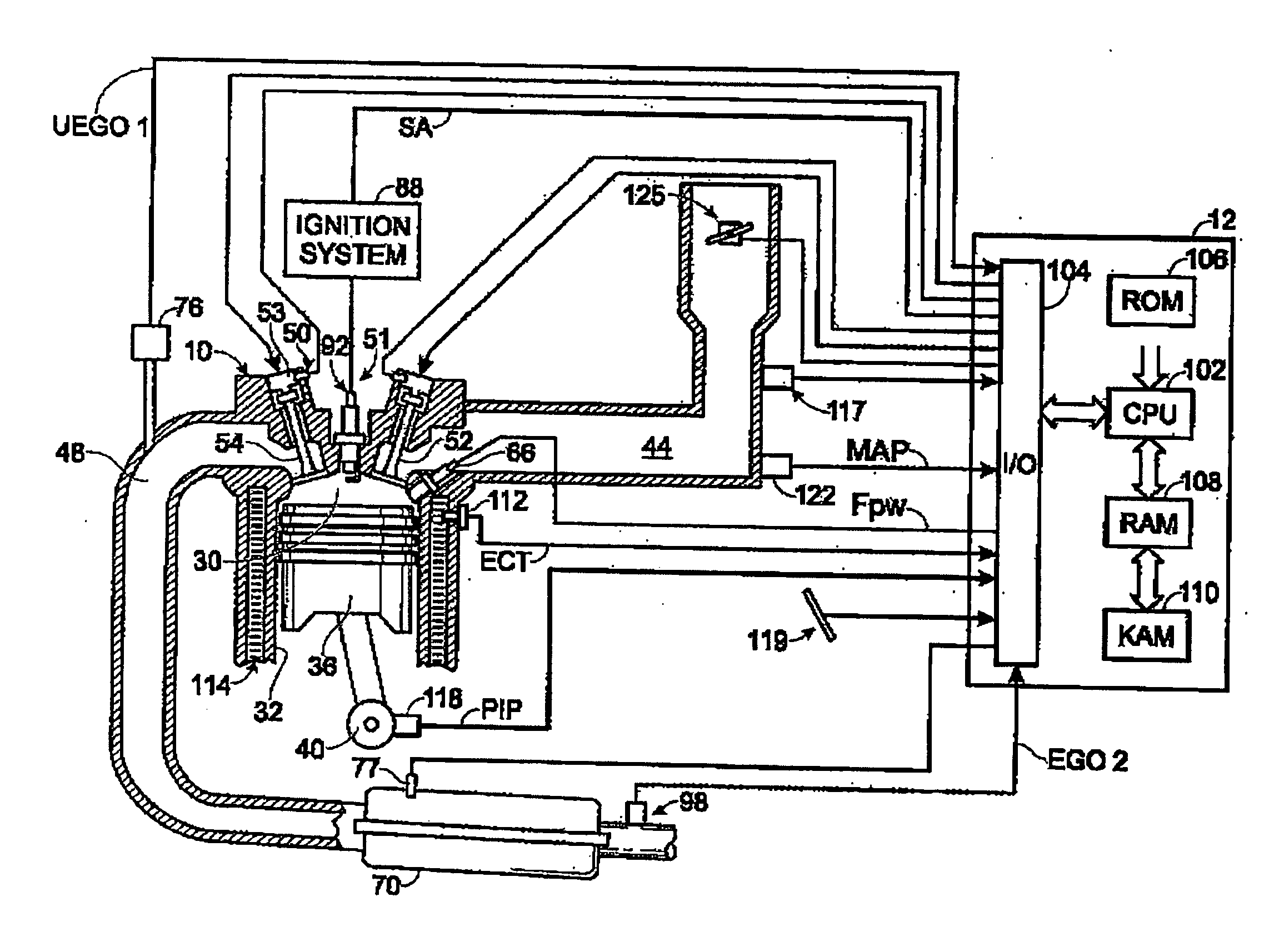
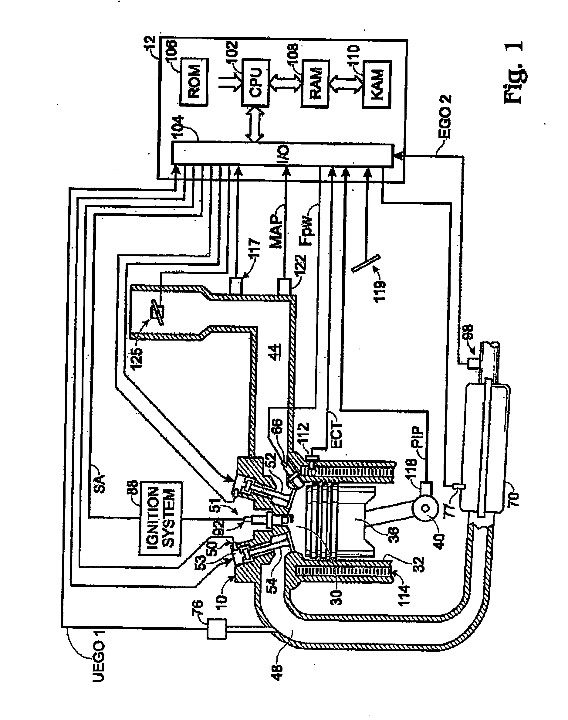
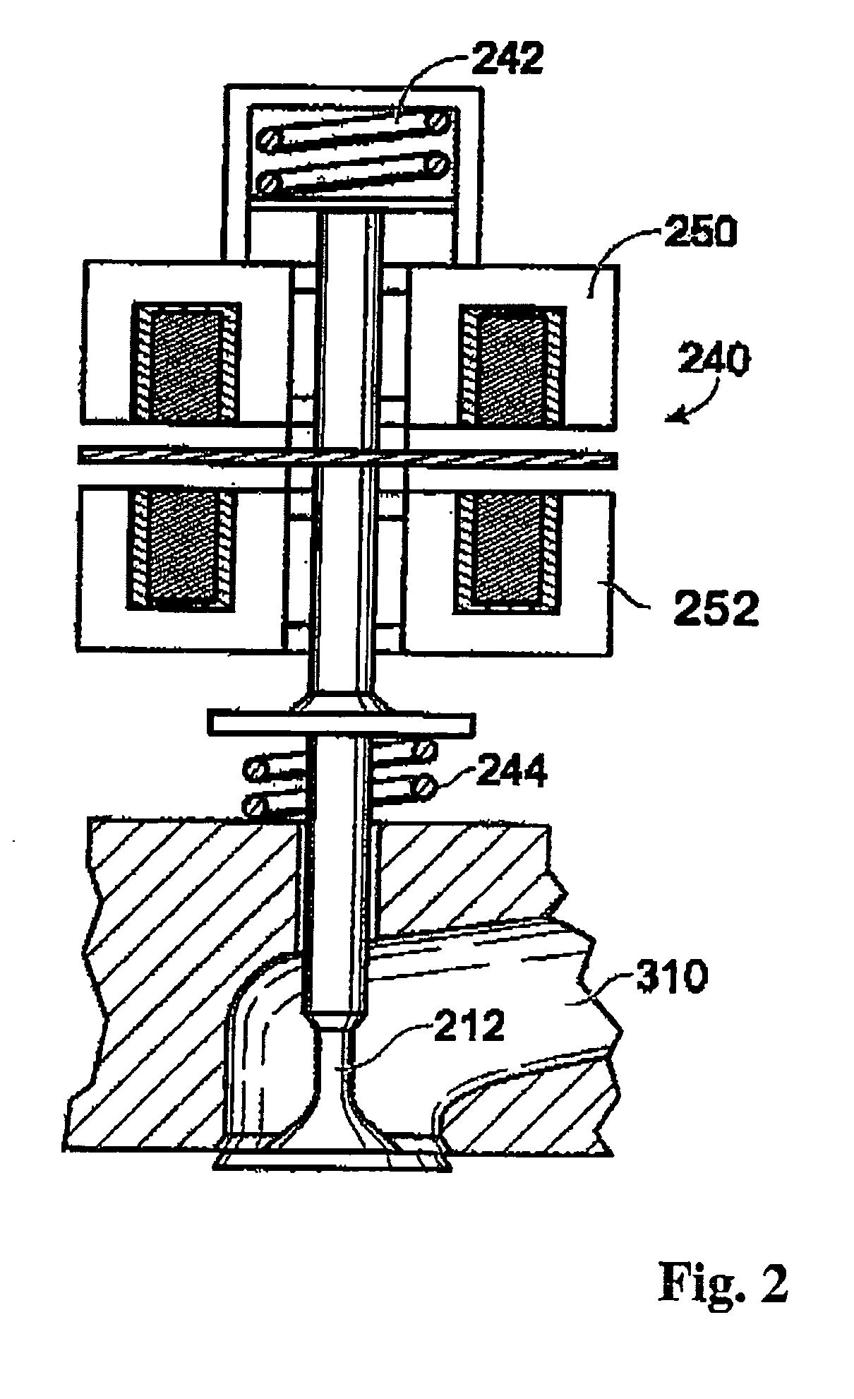
[0015] Referring to FIG. 1, internal combustion engine 10, comprising a plurality of cylinders, one cylinder of which is shown in FIG. 1, is controlled by electronic engine controller 12. Engine 10 includes combustion chamber 30 and cylinder walls 32 with piston 36 positioned therein and connected to crankshaft 40. Combustion chamber 30 is shown communicating with intake manifold 44 and exhaust manifold 48 via respective intake valve 52 an exhaust valve 54. Each intake and exhaust valve is operated by an electromechanically controlled valve coil and armature assembly 53, such as shown in FIG. 2. Armature temperature is determined by temperature sensor 51. Valve position is determined by position sensor 50. In an alternative example, each of valves actuators for valves 52 and 54 has a position sensor and a temperature sensor. In still another alternative, one or more of intake valve 52 and / or exhaust valve 54 may be cam actuated, and be capable of mechanical deactivation. For example...


PUM


Abstract

A method for controlling engine torque during disruption of a primary communication link between an engine control unit and a valve control unit in an engine is provided. The method includes determining disruption of the primary communication link between the engine control unit and the valve control unit, operating a preset valve timing schedule upon determination of disruption of the communication link between the engine control unit and the valve control unit; and sending a status message from the valve control unit to the engine control unit regarding the operational status of the valve control unit.

Description

FIELD [0001] The present application relates to a system and method for controlling engine torque. BACKGROUND AND SUMMARY [0002] Operation of an engine may be improved by accurately delivering a desired engine torque, such as via valve operation and / or throttle control. For example, varying the valve timing may result in rapid and accurate control of the engine torque. [0003] In some cases, valve timing may be managed by a valve control unit (VCU). An engine control unit (ECU) may relay to the valve control unit desired / actual valve timing information. In one example, the engine control unit is linked to the valve control unit through a communication link which enables the engine control unit to provide commands to control operation of the valve control unit. The control of operation of the valve control unit enables selective management of the valve timing which may enhance operation of the engine. The engine control unit and valve control unit may be coupled through a dedicated co...

Claims


Application Information

Patent Timeline
Patent Type & Authority Applications(United States)
IPC IPC(8): B60T7/12
CPCF02D41/266F02D2041/001F02D2041/227F02D41/22
Inventor GIBSON, ALEXTHOMAS, JOSEPH L.WANG, YANMOORHEAD, BRIAN C.WINSTEAD, VINCE
Owner FORD GLOBAL TECH LLC
Why Eureka
Try Eureka