Ultra-tightly coupled GPS and inertial navigation system for agile platforms

a technology of inertial navigation and tight coupling, applied in the direction of navigation instruments, instruments, process and machine control, etc., can solve the problems of gps system noise, loss of signal tracking, and inability to provide a standalone correct solution for gps system, so as to reduce computation time, improve phase and frequency lock, and remove noise

Inactive Publication Date: 2007-05-24
THE BOEING CO
View PDF5 Cites 270 Cited by
  • Summary
  • Abstract
  • Description
  • Claims
  • Application Information

AI Technical Summary

Benefits of technology

[0010] One of the operations carried out in such a UTC GPS / inertial system is that of determining a parameter known as the pseudo range residual (RR). It may be derived from so-called in-phase (I) and quadrature phase (Q) components of a properly-tracked and synchronously-demodulated GPS signal. In accordance with a first aspect of the present invention, a curve fitting mechanism such as a least means square (LMS) curve fitting mechanism is used to find a second order or third order, magnitude-versus-time polynomial that mathematically correlates to carrier phase and / or code phase change of an obtained set of m digital samples from received GPS signals. The value of m can be adjusted so that the rate of production of GPS solutions closely matches solution input rates of other modules in the system. The fitted polynomial can be used to predict the over-time trajectory of the range residual parameter (RR) and to thereby predict Doppler effects expected for GPS carrier frequency and for GPS code phase. In one embodiment, the utilized samples represent integrated correlations of the in-phase (I) and quadrature phase (Q) of received GPS signal components, where the latter components are correlated relative to differently delayed versions (E=early, L=late, P=prompt) of a locally generated, pseudorandom code sequence (PRN). Curve-fitting coefficients representing range residual and rate of change of the RR for each GPS channel are solved for in respective ones of a plurality of range residual extractors (RRE's) and the plural solutions are then forwarded to a relatively slow-cycling Error Kalman Filter (Big EKF). The Big EKF derives and estimates correction signals from the plural RRE solutions and then sends the correction signals to a faster-cycling, inertial navigation module (INM) and to a faster-cycling, GPS tracking predictor, for assisting in the generation of an integrated navigation solution and in the generation of a prediction of GPS line-of-sight (LOS) range shift and Doppler shifts. The curve fitting mechanism in the RRE operates to remove noise from the received GPS sample data. The tightness of the fit (covariance) of the curve fitting process may be used to indicate what signal to noise ratio was present and thus how reliable or how certain the curve fitting solution is. The curve fitting mechanism allows for different output sampling rates (different rates at which the fit-derived RR and RR rate are output) because a time-backwards span of curve fitting operations can be adjusted to use a different number (m) of samples per curve fitting and to thus serve different input sample rates of different applications (e.g., the slow-cycling Error Kalman Filter). RRE extractions can be performed in parallel for respective GPS channels, thereby reducing computation time and freeing the EKF from managing each GPS channel individually.
[0011] Another of the operations carried out in a UTC GPS / inertial system is that of feeding a navigation solution signal, at an IMU-dictated sampling rate, to a GPS tracking predictor so that the predictor can use the navigation solution to help it predict how various GPS space vehicles (SVs) are going to shift in relative position and relative velocity with respect to the agile platform on which the predictor and IMU are mounted. In such an intercoupling of IMU and GPS operations, the relative location (including attitude) of the platform, relative to the SV constellation, may be derived from the latest output sample of the navigation solution signal and the propagation of earlier tracked locations of the utilized GPS constellation of SVs. The relative position and velocity information (related to RR and RR rate) extracted from this intercoupled operation may be used to generate antenna selection and direction corrections and carrier phase and code phase and Doppler shift corrections. However, the problem is that the IMU may not be generating navigation solutions fast enough to keep up with the GPS carrier and code shifting relative to the rate of platform position and attitude changes. In accordance with one embodiment of the present invention, Doppler shift corrections (which in turn, define apparent frequency variation in the GPS carrier) are generated by the GPS tracking predictor at a substantially higher sampling rate (e.g., 1000 Hz, 500 KHz) than the sampling rate (e.g., 100 Hz) at which navigation solutions are produced by the navigation module (INM). The higher output sampling rate(s) of the GPS tracking predictor allows a highly-agile platform system to maintain a better phase and frequency lock on incoming GPS carrier signals and their embedded navigation data.
[0012] In accordance with another aspect of the invention, compensating corrections for drift of clock bias, of data synchronization latency, and of sensor latency are provided so as to improve the accuracy of various signals within the UTC system.

Problems solved by technology

One problem that GPS systems face is loss of signal tracking.
If signals are lost from one or more of a set of in-view GPS satellites, for whatever reason (e.g., jamming, interference, lack of satellite within antenna field-of-view), it may become difficult or impossible for the GPS system to provide a standalone correct solution for object location in three dimensional (3D) space.
Another drawback of using GPS alone is its low dynamic bandwidth.
This makes a standalone GPS system insufficient for navigation and control of fast-moving and / or highly agile platforms.
One problem which inertial measurement systems face is drift over time without error bounding.
Tiny errors in the measurement of platform accelerations and / or attitude rate integrate over time and can therefore produce significant positional and / or velocity errors.
However, the problem is that the IMU may not be generating navigation solutions fast enough to keep up with the GPS carrier and code shifting relative to the rate of platform position and attitude changes.

Method used


Image

  • Ultra-tightly coupled GPS and inertial navigation system for agile platforms
  • Ultra-tightly coupled GPS and inertial navigation system for agile platforms
  • Ultra-tightly coupled GPS and inertial navigation system for agile platforms

Examples


embodiment 200

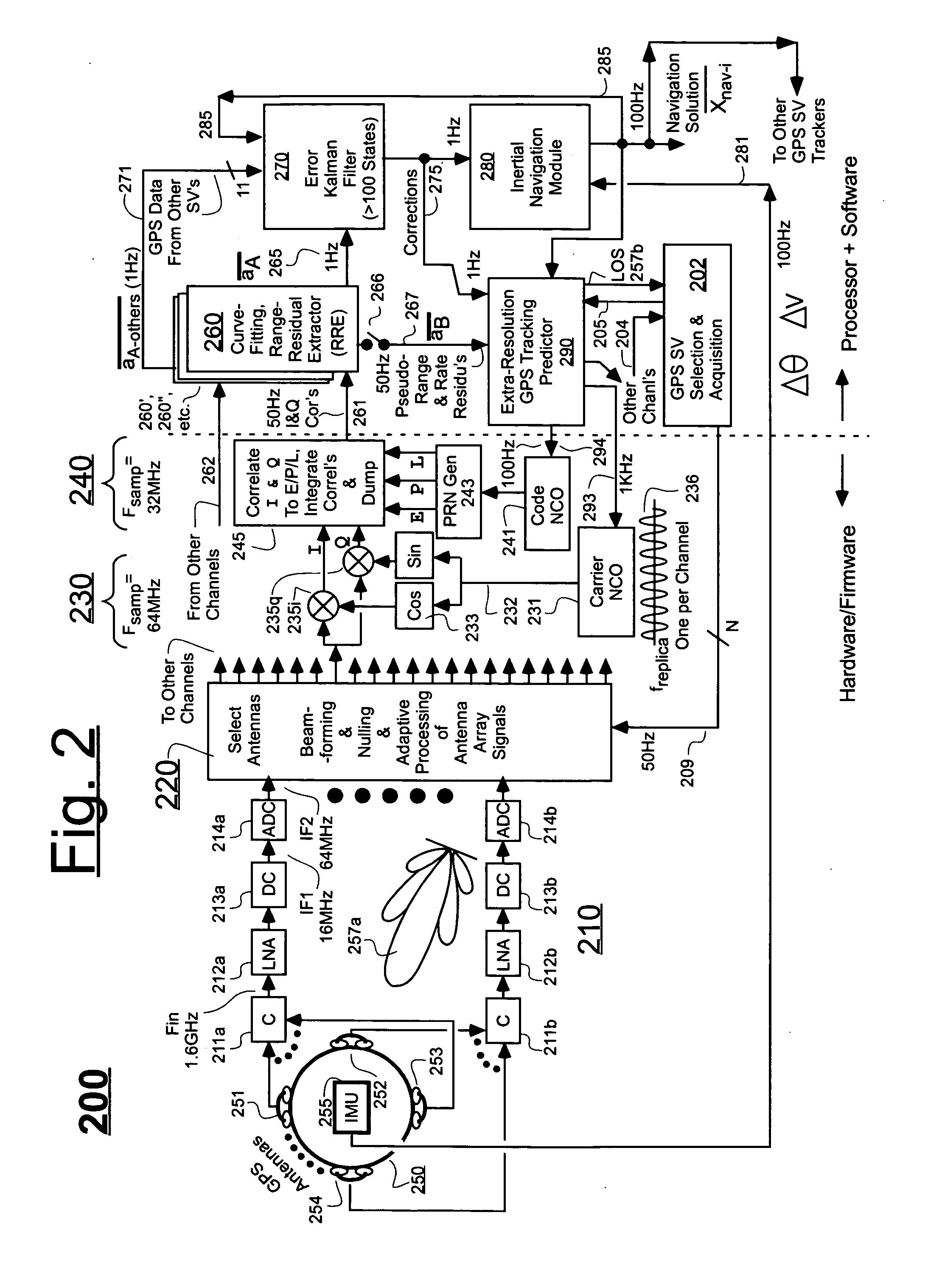
[0044] The processing of only one of the GPS channels will now be described for understanding of the carrier lock-on section 230. It is to be understood that the same structure is repeated for each of other GPS channels but these are not shown in order to preserve illustrative clarity. A GPS channel may be defined as corresponding to a given GPS frequency band and also to a given PRN code sequence. Typically, for each given GPS vehicle, a different PRN code sequence is assigned for each of that vehicle's output bands. Each given GPS vehicle will typically have more than one output channel associated with it. For example, if there are 12 in-view vehicles and each transmits on the L1 and L2 bands, there can be a total of 24 received channels (two for each GPS vehicle). The on-platform system 200 of FIG. 2 tries to generate a local and respective, carrier replica signal 236 for each of its active GPS channels. Thus carrier lock-on is performed on a per-channel basis in this embodiment ...

embodiment 400

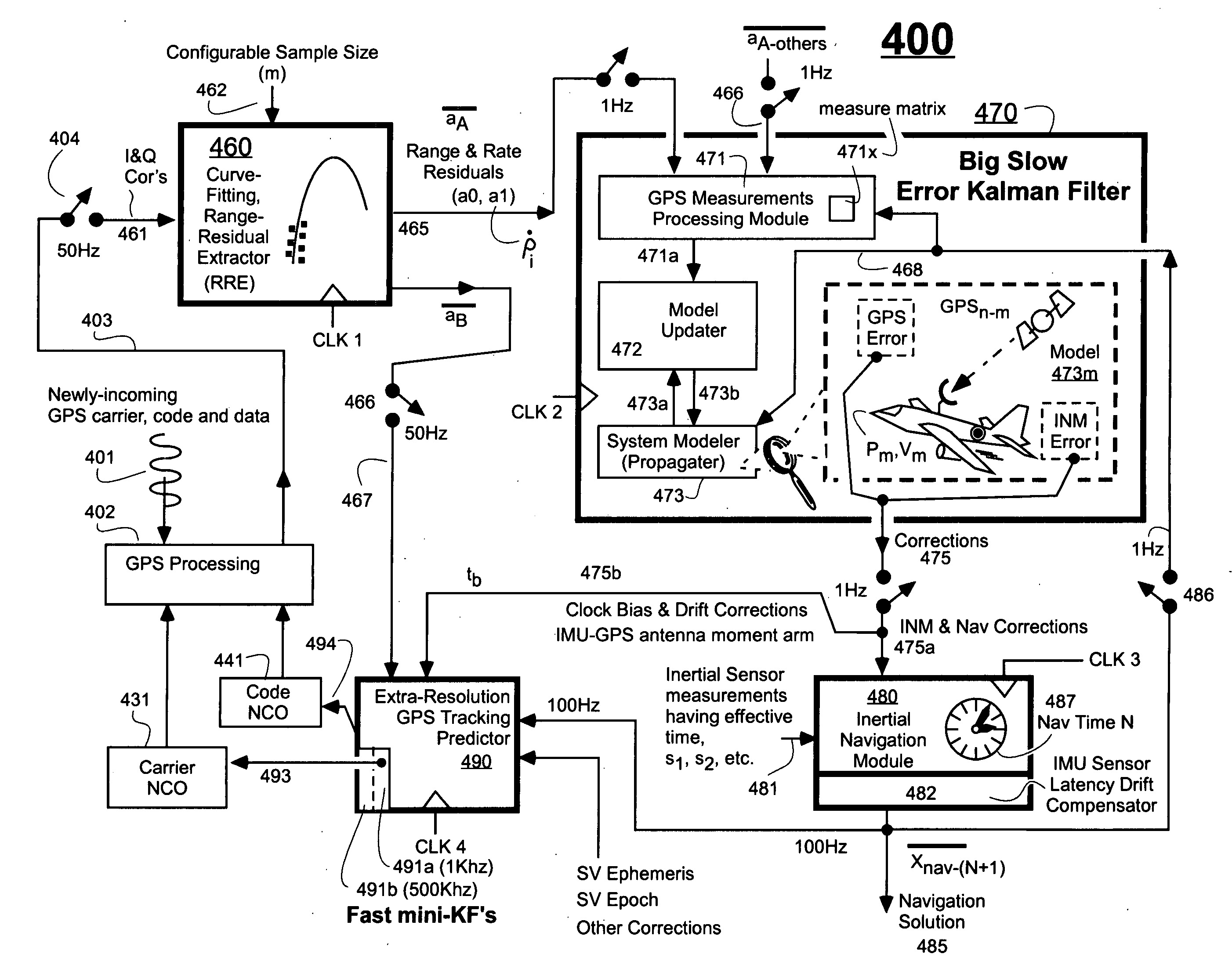
[0069] Referring to FIG. 4A, in the illustrated embodiment 400, all four of the main modules (460, 470, 480 and 490—these correspond to 260, 270, 280 and 290 of FIG. 2) operate in rough synchronism with one another even though some may internally step forward faster than the others. The big EKF 470 produces a new corrections 475 once every 1000 ms (1 Hz rate). The curve fitting RRE 460 has its internal m value adjusted so as to also produce new set of GPS-based measurement residuals once every 1000 ms (1 Hz rate). Even though the internal timing clock 487 of the INM 480 triggers 100 times faster (at a 100 Hz rate) to produce new navigation solution samples onto line 485 every 10 ms, a 1 Hz sampling switch 486 is interposed between the INM 480 and the big EKF 470 so that the EKF 470 receives the latest navigation solution for its internal line 468 only once every 1000 ms (1 Hz rate). The big EKF 470 of this embodiment cannot absorb new measurement data any faster than this because it...

embodiment 600

[0095] Instead of operating in the frequency domain, the 2-stage carrier wipe-off embodiment 600 of FIG. 6 performs a timing shift in the time domain on a per channel basis buy se of the illustrated, carrier phase rotation, and average-down (sum & dump) modules such as 646. To understand on a crude level why this works, it should be appreciated that the feedback loop 675′ that urges the carrier NCO 631 towards approximate, frequency lock-on with the incoming signals of a given band (e.g., L1) is simultaneously performing an approximate, phase lock on. If the replica signal 636 is falling behind the incoming PRN's of the given band (e.g., L1), then the EKF feedback loop signal 675′ will advance the output frequency of NCO 631, thereby causing it to also advance in phase so as to catch up with the incoming PRN streams. Accordingly, the once demodulated outputs 637 of multipliers 635 will be close to being in phase with the output sine and cosine waveforms of generators 633. A small ph...


PUM


Abstract

An Ultra-Tightly Coupled GPS-inertial navigation system for use in a moving agile platform includes a range residual extractor that uses best curve fitting of a third order polynomial for estimating range residual. The curve-fitted residual is used to update an error Kalman filter. The error Kalman filter includes correction for navigation solution, and IMU and GPS parameters. The navigation solution together with GPS parameter corrections are used in a Tracking Predictor to generate high-sampling-rate carrier and code replicas. The curve-fitting error covariance indicates signal to noise ratio for the tracked GPS signal and may be used for early indication of interference or jamming.

Description

FIELD OF DISCLOSURE [0001] The present invention relates generally to GPS and Inertial navigation systems for use on moving agile platforms (e.g., moving missiles, aircraft or spacecrafts) and more specifically to an ultra-tightly coupled (UTC) GPS / inertial navigating system. CROSS REFERENCE TO PATENTS [0002] The disclosure of the following U.S. patent is incorporated herein by reference: [0003] (A) U.S. Pat. No. 6,516,021 B1, issued Feb. 4, 2003 to Abbott et al. and entitled “Global Positioning Systems and Inertial Measuring Unit UltraTight Coupling Method”. CROSS REFERENCE TO APPLICATIONS [0004] The pending below application is owned by the owner of the present application, and its disclosure is hereby incorporated by reference herein: [0005] (A) U.S. Ser. No. 10 / 647,958 of Hanching Grant Wang et al, filed on Aug. 26, 2003. DESCRIPTION OF RELATED ART [0006] Use of Global Positioning Systems (GPS) for locating an object within the framework of a constellation of GPS satellites is k...

Claims


Application Information

Patent Timeline
Patent Type & Authority Applications(United States)
IPC IPC(8): G01C23/00G01S19/21G01S19/26
CPCG01C21/165G01S19/21G01S19/26G01S19/47
Inventor WANG, HANCHING GRANTDETTERICH, BRUCE CORDELL
Owner THE BOEING CO
Why Eureka
Try Eureka