Method and system for controlling the level of a data signal read from an optical disc

a data signal and optical disc technology, applied in the field of optical recording, can solve the problems of reducing the performance measured in terms of jitter and error rate, preventing the system from quickly responding to defects, and affecting the reading strategy of optical discs, so as to improve the reading strategy and reduce the reflection

Inactive Publication Date: 2007-05-31
KONINKLIJKE PHILIPS ELECTRONICS NV
View PDF3 Cites 0 Cited by
  • Summary
  • Abstract
  • Description
  • Claims
  • Application Information

AI Technical Summary

Benefits of technology

[0017] This information signal is used for indicating the presence of a defect at the surface of an optical disc that results in a reflectivity reduction. This information signal may be used, for example, to improve the reading strategy of the optical disc, for example in jumping the area considered as comprising a defect.

Problems solved by technology

On the other hand, a slow response prevents the system from quickly responding to defects.
If the time constant is reduced, the system becomes jittery, thus degrading the performance which is measured in terms of jitter and error rate.
This known method has its limitations in that the optimal time constant is difficult to define, considering that it should be great to prevent baseline wander, but small to effectively remove undesired low-frequency variations caused by disc defects.

Method used


Image

  • Method and system for controlling the level of a data signal read from an optical disc
  • Method and system for controlling the level of a data signal read from an optical disc
  • Method and system for controlling the level of a data signal read from an optical disc

Examples


Embodiment Construction

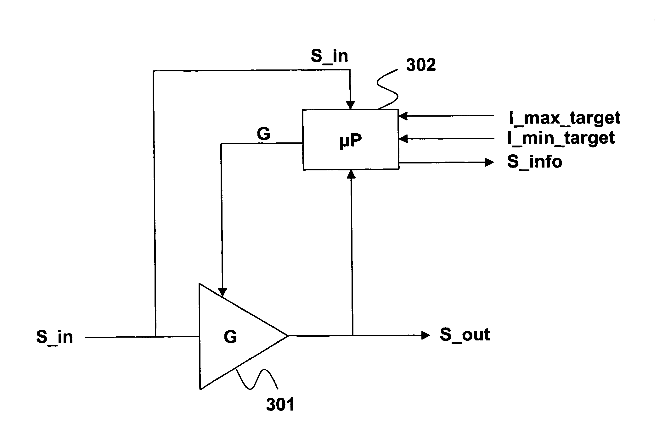
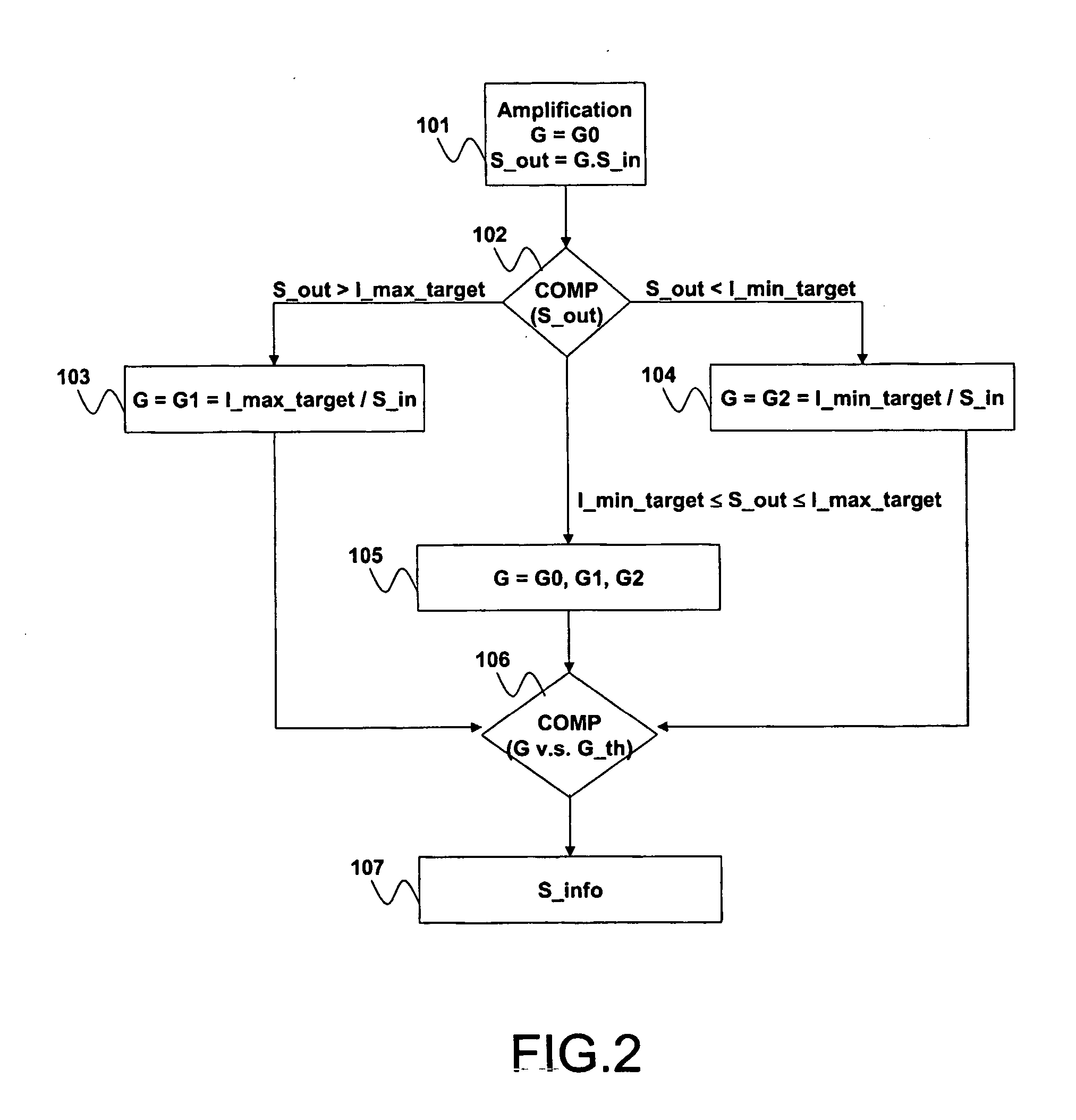
[0024]FIG. 2 is a flowchart of processing steps for controlling the level of an input readout signal S_in read from an optical disc for generating an output readout signal S_out.

[0025] This method comprises a step 101 of amplifying the input readout signal S_in by a gain G for generating the output readout signal S_out. Readout signals are thus linked by the following relation:

S_out=G*S—in  Eq.1

The gain G is initially set to an arbitrary value G0, for example G0=1.

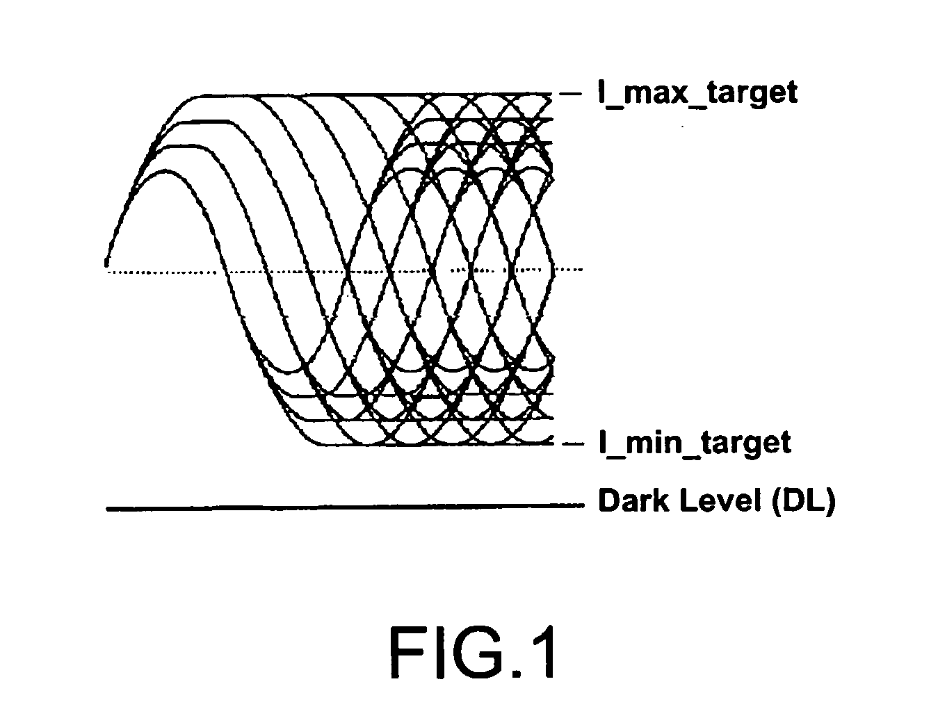
[0026] This method comprises a step 102 of comparing said output readout signal S_out with a maximum target level I_max_target and with a minimum target level I_min_target. The target levels are known, for example, from specifications, or chosen by measurement so as to be close to the maximum and minimum levels of the input readout signal S_in in optimal conditions (i.e. without reduction of the laser beam reflected from the optical disc).

[0027] This method comprises a first step 103 of setting said gain G to a value...


PUM

PropertyMeasurementUnit
gain thresholdaaaaaaaaaa
reflectivityaaaaaaaaaa
time constantsaaaaaaaaaa

Abstract

The invention relates to a method of controlling the level of an input readout signal read from an optical disc. The method proposes to use an amplification step for amplifying the input readout signal by an adjustable gain factor for generating an amplified output readout signal having an amplitude in the range [I min target, I max target]. The value of this gain is derived from a feedback loop control in charge of comparing the level of the output readout signal with that of target levels I min target and I max target, and deriving a gain value taking into account the level of the input readout signal. This loop control renders it possible to clamp the input readout signal, counteracting as a consequence the decrease of the input readout signal in the case of a reflectivity reduction of the optical disc. Use: Optical disc reader.

Description

FIELD OF THE INVENTION [0001] The present invention relates to a method and system for controlling the level of a data signal read from an optical disc. [0002] The present invention also relates to a method of generating an information signal intended to indicate the presence of a defect at the surface of an optical disc. [0003] This invention has many applications in the field of optical recording. BACKGROUND OF THE INVENTION [0004] In optical recording systems such as CD, DVD, or Blue Ray (BD) disc, the information recorded on the optical disc is retrieved from a readout signal, conventionally represented by an eye pattern as illustrated in FIG. 1. Information is often retrieved from a processing chain including a photo detector, a bit detection system, a preamplifier, a gain and level control, an equalizer, a timing recovery system, and an error correction system. [0005] Data information is recorded on the disc, for example, as a series of pits and lands representing binary data ...

Claims


Application Information

Patent Timeline
Patent Type & Authority Applications(United States)
IPC IPC(8): G11B7/00G11B7/005G11B20/10H03G3/20H03G3/30
CPCG11B7/0052G11B20/10009G11B20/10027H03G3/3089G11B2220/2541H03D2200/0025G11B2020/1288G11B20/10G11B7/005H03G3/30H03G3/20
Inventor OTTE, ROB
Owner KONINKLIJKE PHILIPS ELECTRONICS NV
Why Eureka
Try Eureka