Electroluminescent device with quinazoline complex emitter
a technology of electroluminescent devices and quinazoline complexes, which is applied in the direction of discharge tube luminescnet screens, cadmium organic compounds, etc., can solve the problems of large efficiency loss, difficult to synthesize bis-cyclometallated metal complexes, and less stable relative stability of bis-cyclometallated metal complexes, etc., to achieve the effect of useful emission and stability attributes
- Summary
- Abstract
- Description
- Claims
- Application Information
AI Technical Summary
Benefits of technology
Problems solved by technology
Method used
Image
Examples
example 1
Synthesis of Inv-1, fac-tris(2-phenylquinazolinato-N,C2′)iridium(III)
[0287] K3IrBr6 (2.80 g, 3.55 mmol) was placed in a 200 mL round bottom flask with 45 mL of 2-ethoxyethanol, 15 mL water, and 2-phenylquinazoline (8.87 mmol). The mixture was freeze-thaw degassed, and then refluxed for 4 h under nitrogen atmosphere during which time an orange precipitate appeared. After cooling, the precipitate was collected by filtration, washed with 1N HBr(aq), then water, then ethanol, and dried to yield orange tetrakis(2-phenylquinazolinato-N,C2′)(μ-dibromo)diiridium(III) (2.29 g, 94% yield based on iridium).
[0288] Then tetrakis(2-phenylquinazolinato-N,C2′)(μ-dibromo)diiridium(III) (0.85 g, 1.245 mmol) and silver tetrafluoroborate (0.27 g) were placed in a 100-mL round-bottomed flask. Acetonitrile (30 mL) was added and the mixture was freeze-thaw degassed, and then refluxed for 3 h under nitrogen atmosphere. After cooling, the yellow solution was filtered thru celite filter aid to remove white...
example 2
Synthesis of Inv-2, of fac-tris(4-phenylquinazolinato-N,C2′)iridium(III)
[0290] K3IrBr6 (2.755 g, 3.49 mmol) was placed in a 125 mL round bottom flask with 39 mL of 2-ethoxyethanol, 13 mL water, and 4-phenylquinazoline (1.80 g, 8.73 mmol). The mixture was freeze-thaw degassed, and then refluxed for 4 h under nitrogen atmosphere during which time a dark red precipitate appeared. After cooling, the precipitate was collected by filtration, washed with methanol and ligroin, and dried to yield dark red tetrakis(4-phenylquinazolinato-N,C2′)(μ-dibromo)diiridium(III) (2.265 g, 95% yield based on iridium).
[0291] Next, tetrakis(4-phenylquinazolinato-N,C2′)(μ-dibromo)diiridium(III) (0.696 g, 1.02 mmol) and silver tetrafluoroborate (0.218 g) were placed in a 100-mL, round-bottom flask. Acetonitrile (30 mL) was added and the mixture was freeze-thaw degassed, and then refluxed for 3 h under nitrogen atmosphere. After cooling, the red-orange solution was filtered thru celite filter aid to remove ...
example 3
Fabrication of Device 1-1 Through 1-3
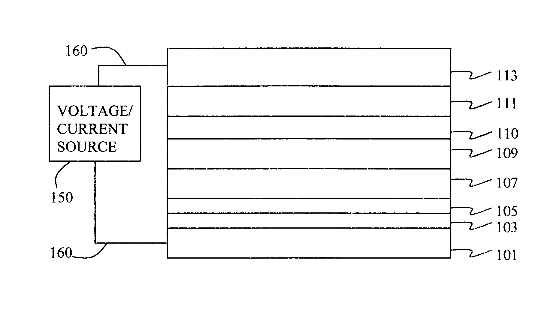
[0293] An EL device (1-1) satisfying the requirements of the invention was constructed in the following manner:
[0294] A glass substrate coated with an 85 nm layer of indium-tin oxide (ITO) as the anode was sequentially ultrasonicated in a commercial detergent, rinsed in deionized water, degreased in toluene vapor and exposed to oxygen plasma for about 1 min.
[0295] a) Over the ITO was deposited a 1 nm fluorocarbon (CFx) hole-injecting layer (HIL) by plasma-assisted deposition of CHF3.
[0296] b) A hole-transporting layer (HTL) of N,N′-di-1-naphthalenyl-N,N′-diphenyl-4,4′-diaminobiphenyl (NPB) having a thickness of 150 nm was then evaporated from a tantalum boat.
[0297] c) A 35 nm LEL comprised of CBP (4,4′-N,N′-dicarbazole-biphenyl) and 4 wt % of the phosphorescent dopant Inv-1 were then deposited onto the hole-transporting layer. These materials were also evaporated from graphite boats.
[0298] d) A 10 nm hole blocking layer of bis(2-methyl-8-qu...
PUM
| Property | Measurement | Unit |
|---|---|---|
| thick | aaaaa | aaaaa |
| thickness | aaaaa | aaaaa |
| work function | aaaaa | aaaaa |
Abstract
Description
Claims
Application Information
 - R&D
- Intellectual Property
- Life Sciences
- Materials
- Tech Scout
- Unparalleled Data Quality
- Higher Quality Content
- 60% Fewer Hallucinations
Browse by: Latest US Patents, China's latest patents, Technical Efficacy Thesaurus, Application Domain, Technology Topic, Popular Technical Reports.
© 2025 PatSnap. All rights reserved.Legal|Privacy policy|Modern Slavery Act Transparency Statement|Sitemap|About US| Contact US: help@patsnap.com


