System for variable valvetrain actuation

a variable valvetrain and valvetrain technology, applied in the direction of valve details, valve arrangements, valve drives, etc., can solve the problems of requiring significantly more power than a conventional fixed-state engine, the cost of a “camless” system is usually on par with the cost of an entire conventional engine itself, and the total mass moment of inertia is much lower. , the effect of less challenge in spring design

Inactive Publication Date: 2007-06-07
DELPHI TECH IP LTD
View PDF3 Cites 46 Cited by
  • Summary
  • Abstract
  • Description
  • Claims
  • Application Information

AI Technical Summary

Benefits of technology

[0016] Compared to prior art devices, an important advantage of the present mechanism is its simplicity. The input and output oscillators of prior art mechanical, continuously variable valvetrain devices, such as the SSCR and the DCDVVT, have been combined into one moving part. Due to its inherent simplicity, the present invention differs significantly from the original SSCR device in its assembly procedure for mass production. With only one oscillating member, the present invention accrues significant cost, manufacturing and mechanical advantages over these previous designs. Further, a VVA device in accordance with the present invention does not “hang” from the camshaft, as was the case with these other mechanisms and therefore is not a parasitic load on the camshaft. Since the present invention ha...

Problems solved by technology

One of the drawbacks inhibiting the introduction of a gasoline Homogeneous Charge Compression Ignited (HCCI) engine in production has been the lack of a simple, cost effective and energy efficient Variable Valvetrain Actuation (VVA) system to vary both the exhaust and intake events.
Many electro-hydraulic and electro-mechanical “camless” VVA systems have been proposed for gasoline HCCI engines, but while these systems may consume less or equivalent actuation power at low engine speeds, they typically require significantly more power than a conventional fixed-lift and fixed-duration valvetrain system to actuate at mid and upper engine speeds.
Moreover, the cost of these “camless” systems usually is on par with the cost of an entire conventional engine itself.
As the cost of petroleum continues to rise from increased global demands and limited...

Method used


Image

  • System for variable valvetrain actuation
  • System for variable valvetrain actuation
  • System for variable valvetrain actuation

Examples


Embodiment Construction

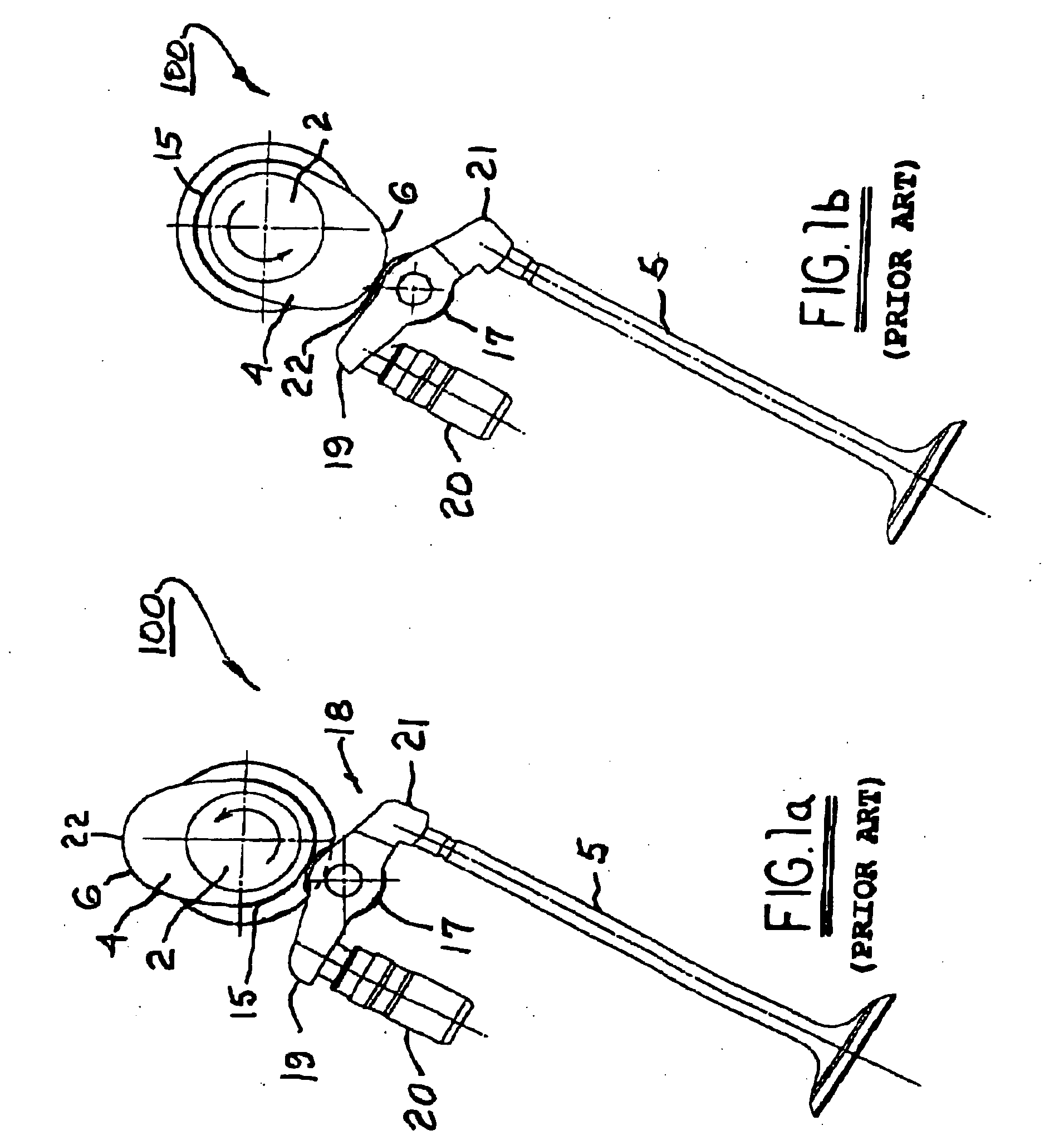
[0039] The benefits and advantages of a VVA system in accordance with the invention may be better appreciated by first considering a prior art engine valvetrain without VVA.

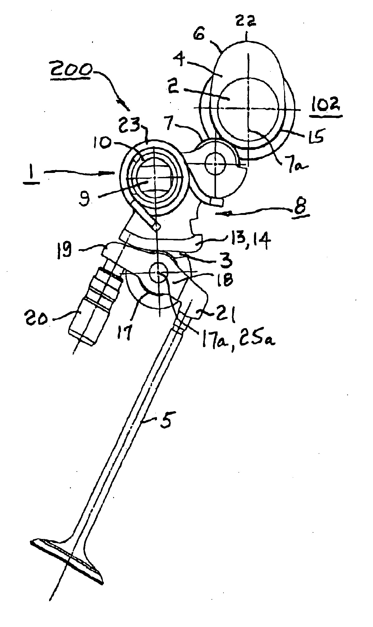
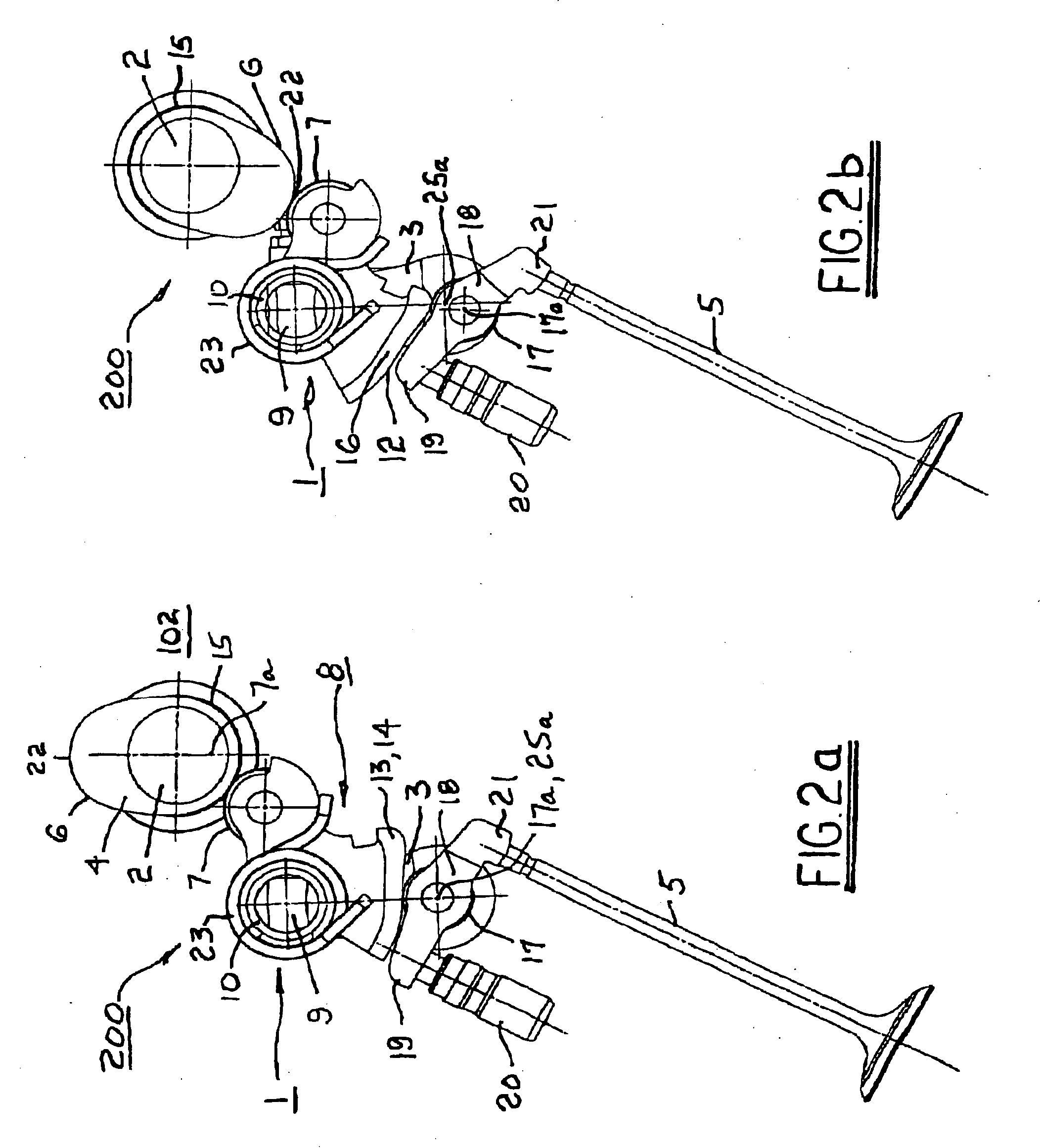
[0040] Referring to FIGS. 1a and 1b, a prior art valvetrain 100 comprises an input engine camshaft 2 having a cam lobe 4. Lobe 4 is defined by a profile having a base circle portion 15, an opening flank 6, and a nose portion 22. A roller finger follower (RFF) 18 includes a centrally mounted roller 17 for following cam lobe 4 and is pivotably mounted at a first socket end 19 on a hydraulic lash adjuster 20. A second pallet end 21 of RFF 18 engages the stem end of an engine valve 5. When RFF 18 is on the base circle portion 15, valve 5 is closed, as shown in FIG. 1. As camshaft 2 rotates counterclockwise, RFF 18 begins to climb opening flank 6, forcing valve 5 to begin opening. When RFF 18 reaches nose portion 22, valve 5 is fully open, as shown in FIG. 2. Further rotation of camshaft 2 causes valve 5 to gradually...


PUM


Abstract

An electromechanical VVA system for controlling the poppet valves in the cylinder head of an internal combustion engine. The system varies valve lift, duration, and phasing in a dependent manner for one or more banks of engine valves. A rocker subassembly for each valve or valve pair is pivotably disposed on a control shaft between the camshaft and the roller finger follower. The control shaft may be displaced about a pivot axis outside the control shaft to change the angular relationship of the rocker subassembly to the camshaft, thus changing the valve opening, closing, and lift. A plurality of control shafts for controlling all valvetrains in an engine bank defines a control shaft assembly. The angular positions of the individual control shafts may be tuned to optimize the valve timing of each cylinder. The system is applicable to the intake and exhaust camshafts of diesel and gasoline engines.

Description

TECHNICAL FIELD [0001] The present invention relates to valvetrains of internal combustion engines; more particularly, to devices for controlling the timing and lift of valves in such valvetrains; and most particularly, to a system for variable valvetrain actuation wherein electromechanical means for variable actuation is interposed between the engine camshaft and the valvetrain cam followers to vary the timing and amplitude of follower response to cam rotation. BACKGROUND OF THE INVENTION [0002] One of the drawbacks inhibiting the introduction of a gasoline Homogeneous Charge Compression Ignited (HCCI) engine in production has been the lack of a simple, cost effective and energy efficient Variable Valvetrain Actuation (VVA) system to vary both the exhaust and intake events. Many electro-hydraulic and electro-mechanical “camless” VVA systems have been proposed for gasoline HCCI engines, but while these systems may consume less or equivalent actuation power at low engine speeds, they...

Claims


Application Information

Patent Timeline
IPC IPC(8): F01L1/34F01L1/02F01L1/18
CPCF01L1/024F01L1/185F01L1/267F01L13/0021F01L13/0063F01L2013/0068F01L2013/0073F01L2105/00F01L2305/00
Inventor ROHE, JEFFREY D.ROE, RICHARD B.LEE, JONGMINGUTTERMAN, JEFFREY
Owner DELPHI TECH IP LTD
Why Eureka
Try Eureka